Home
Info info@electronicsandbooks.com
Electronics for sale
Change date = 20070624 13:18:00
Art.Nr. 31
Type 1115/116
Brand - Merk US Army
Article - Artikel Frequency Standard
Price - Prijs 35,00 Euro
Stock - Voorraad 1
Condition - Conditie New
Size - Grootte H - H 130 W - B 190 D - D 70 mm
Documentation None
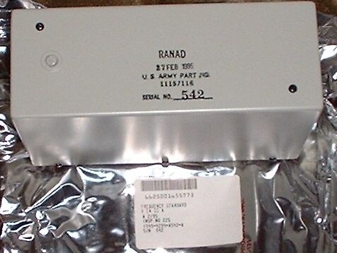
Title US Army 1115/116 Frequency Standard [31]
--------------------------------------------------------------------------------
Dated 27 feb 1995
Connector : D25 male
Frequency Standard
FSN 6625-00-165-5773
1549-4010-A546-A
RANAD
U.S. Army Part No 1115/116
+Brooke Clarke, N6GCE
Description
It measures 7 5/16" x 2 3/4" x 4 9/16" tall.
On the bottom is a DB-25(m) connector and on the top there is an access
screw to a trim pot.
Inside there are 4 double sided 6 5/8" x 2 1/4" printed circuit boards.
The top of the can has a date of 24 FEB 1994.
The A2 board says "Control Science Corporation"
Note: When seperating the boards it's possible for the socket pins to
fall out. Since all locations are not used it may be very difficult to get
them back into the correct holes.
There are two kinds of pins for the Bendix connector, one type solderes
to the board and has a pin going down and a socket pointing up. The other type
solderes to the board and has a pin going down but is short without any socket.
All installed pins make a connection to the PCB & Bendix connector below, but
only some connect to the board above.
Best Guess as to function
Based on the below observations I think this is an audio tone generator
where the tone is selected by digital relay coil logic inputs to the DB-25
connector and the output is on one of the DB-25 pins. With 11 relays there
might be 10 or 11 different tones available. Or maybe a binary sequence of
tones where there are 2E11 possible tones?
The crystal is not ovenized so this is not a very high stability source, but
a crystal would provide better stability than an RC type audio oscillator. The
adjustmet pot on the top board is not for triming the crystal which has it's
own glass trimmer, unless the pot is for fine trimming and the glass cap is
coarse tuning.
DB-25 pins 1 to 11 are relay coil -15 VDC inputs with 12 being the common
+ground
DB-25 pins: 15, 17, 20, 21, 24 and 25 are power supply related.
DB-25 pins: 13, 14, 22 and 23 have no connection (nc).
DB-25 pins 16, 18 and 19 have an unknown function, at least one is an
output
DB-25 pin 12 is the common for all the relay 1030 Ohm coils. It takes 12
VDC to jsut trip the relay and abut 15 VDC for solid operation. With a 1 k Ohm
coil they pull about 15 ma.
Best Guess at powering up
The Logic supply appears to be + 7 VDC @ 270 ma on DB-25 pin # 24 and the
ground return on DB-25 pin # 25. This causes the yellow wire on the pass
transistor to be at 5.2 VDC.
But the two model 1682 +/- 25 VDC converters are not getting any input,
hence they don't have any output.
Maybe one of the 3 unknown pins is some type of enable that activates the
+/- 25 VDC converters?
Level 0
The lower Aluminum plate that holds the DB-25 plug also has a metal box with
three wires going to it, purple is ground and a purple not ground and yellow,
most likely a power supply pass transistor. There is a Bendix Scintilla 30 pin
socket and all the printed circuit boards have a similar socket with both male
and female connection so that they can be stacked. The Bendix part number of
this one is 10-299812-30.
Pin #
Wire Color
Function
Bendix Pin #
all Up
Level 1 PCB
1
White
L4 Relay 500
7u
2
White
L4 Relay 498
8u
3
White
L4 Relay 502
29u
4
White
L4 Relay 497
10u
5
White
L4 Relay 499
16u
6
Blue
L4 Relay 501
14u
7
Blue
L4 Relay 496
17u
8
Blue
L4 Relay 495
12u
9
Blue
L3 Relay far from "A2"
3u
10
Gray
L3 Relay middle
2u
11
Gray
L3 Relay near "A2" mark
19u
12
Brown
Com all Relay coils
20u
13
nc
nc
nc
14
nc
nc
nc
15
Red
+25 VDC test point
1u
1682 OUPT
1682 +25V
16
Purple
?
21u
L1 IC30 BB
17
Green
-25 VDC test pint
30u
1682 -25V
18
Yellow
?
25u
L1 IC31a
19
Yellow
?
23u
L1 IC31b
20
Black
op amp common
4u
1682 COM
21
Black
Case Ground
level 1-2 shield
level 3&4 can
nc
22
nc
nc
nc
23
nc
nc
nc
24
Purple
+7 VDC@ 270 ma in
PS xistor term
9u
25
Purple
PS xistor case
Power Supply
GROUND
11u
TTL IC gnd
nc
Yellow
PS xistor term
+ 5.2 V main PS
24u
TTL IC +5V
Bendix connector has no pins in positions 5, 6, 13, 15, 18, 22, 26, 27 and
28.
All 3 erminals of the PS xixtor are floated from case ground.
Level 1
This lowest PCB contains a mix of ICs and discrete analog components. On
the bottom is a MDI Modular model 1682 DC to DC converter with markings, +in,
-in, Trim, Oupt, -25V, Com, +25V.
Image of Level 1 PCB, Alternate Level 1 image
The ICs on this baord are marked:
IC# # Pins Marked Commercial
21 14 S8870A
22 14 S8280A
23 14 S8870A
24 14 S8280A
25 14 NA 544121n
26 14 S8280A
27 14 S8280A
28 14 S8826A
29 8 TO5 NA 52710L op amp
30
8
BB
31
4
Blk Plastic
box
Bendix Connector
Bendix Pin #
Description
Up
Description
Down
1ud
L4 DC module +25 out
L1 DC module +25 out
"
2ud
L3 Relay middle
"
3ud
L3 Relay far from "A2"
"
4ud
L4 DC module common
L1 DC module common
op amp common
"
5ud
6ud
7ud-nc
L4 Relay 500 coil
"
8ud-nc
L4 Relay 498 coil
"
9ud
10ud-nc
L4 Relay 497 coil
"
11ud
"
L0 PS Gnd
12ud-nc
L4 Relay 495 coil
"
13
nc
14ud-nc
L4 Relay 501 coil
"
15
nc
16ud-nc
L4 Relay 499 coil
"
17ud-nc
L4 Relay 496 coil
"
18ud=23
L1 IC31b
19ud
L3 Relay near "A2" mar"
"
20ud
L4 Relay Coil Common
"
21d=27
open
L1 IC30 BB
22ud
L1 module Output
23d=18
open
L1 IC31b
24ud
"
L0 + 5.2 V
25d=26
open
L1 IC31a
26ud=25
L1 IC31a
27ud=21
L1 IC30 BB
28ud
29ud-nc
L4 Relay 502 coil
"
30ud
L4 DC module -25 V out
L1 DC module -25 V 0ut
"
31
nc
ud-nc means Up Down pin installed, but no connection on this level
Level 2
Between level 1 and level 2 is a thin fiberglass board with its ground
shield connected by wire to ground. The Level 2 PCB has a mix of 8 ICs and
discrete analog components as well as a crystal marked 1M000000 (maybe 1 MHz).
Adjacent to the crystal is a glass variable capacitor. There are 8 2N222
transistors each surrounded by a cap, 3 resistors and a diode. and a couple of
metal can op amps.
Image of Level 2 PCB, Alternate Level 2 image
The ICs on this baord are marked:
IC #
# Pins
Marked
Commercial
1
14
S8480A
2
14
S8826A
3
14
S8488A ?
4
14
S8808A
5
14
S8826A
6
14
S8826A
7
14
S8826A
8
14
S8480A
9
14
S8480A
10
8 TO5
NA
52741AL
op amp
Bendix Connector
Bendix Pin #
Dexcription
Up
Description
Down
1ud
L4 DC module +25 out
"
2ud-nc
L3 Relay middle
"
3ud-nc
L3 Relay far from "A2"
"
4ud
L4 DC module common
"
5d
open
6d
open
7ud
L4 Relay 500 coil
"
8ud
L4 Relay 498 coil
"
9d
open
10ud
L4 Relay 497 coil
"
11d
open
L0 PS Gnd
12ud
L4 Relay 495 coil
"
13
nc
14ud
L4 Relay 501 coil
"
15
nc
16ud
L4 Relay 499 coil
"
17ud
L4 Relay 496 coil
"
18ud
19ud-nc
L3 Relay near "A2" mark
"
20ud
L4 Relay Coil Common
"
21ud
L4 caps
"
22d
open
23ud
L4 resistors
L2 741 Out
24d
open
L0 + 5.2 V
25ud
L4 Main top Pot
"
26d
open
27d
open
28d
open
29ud
L4 Relay 502 coil
"
30ud
L4 DC module -25 V out
"
31
nc
Level 3 Board A2 CSC p/n C-005
Level 3 and Level 4 PCBs are enclosed in a metal shielding can. The Level 3
PCB has 3 relays and a number of high Q capacitors, a couple of tublar caps
marked .99 MFD 100 V.D.C and a couple of smaller ones marked 9100+/- 1% and
others marked 91000+/- 1% and many more smaller ones. Two glass piston trimmer
caps also on the end of this board.
This board only has capacitors and relays, no active components.
The Relay coil common is Bendix pin #20 like on the level 4 board and the
three coils are on Bendix pins 2,3 and 19
Bendix Pin #
Description
Up
Description
Down
1ud-nc
L4 DC module +25 out
"
2d
open
L3 Relay middle
3d
open
L3 Relay far from "A2"
4ud
L4 DC module common
"
5
nc
nc
6
nc
nc
7ud-nc
L4 Relay 500 coil
"
8ud-nc
L4 Relay 498 coil
"
9d
open
10ud-nc
L4 Relay 497 coil
"
11d
open
12ud-nc
L4 Relay 495 coil
"
13d
open
14ud-nc
L4 Relay 501 coil
"
15d
open
16ud-nc
L4 Relay 499 coil
"
17ud-nc
L4 Relay 496 coil
"
18
nc
nc
19d
open
L3 Relay near "A2" mark
20ud
L4 Relay Coil Common
"
21ud-nc
L4 caps
"
22
nc
nc
23ud-nc
L4 resistors
"
24ud
L4 caps
"
25ud-nc
L4 Main top Pot
"
26
nc
nc
27
nc
nc
28ud
L4 DC module + IN
"
29ud-nc
L4 Relay 502 coil
"
30ud-nc
L4 DC module -25 V out
"
31
nc
nc
ud-nc means no connection on this level
Level 4 Board A1 CSC p/n C-004
This is the top PCB that has the trimmer pot that can be accessed through
the screw in the top outer cover. There are 8 relays on this layer and by each
one there are high Q caps. It appears that the main purpose of this board is
to switch caps. A MDI Modular model 1682 DC to DC converter is also on this
board, +in, -in, Trim, Output, -25V, Com, +25V are the labels. Another of these
is on the lowest PCB.
There are no ICs on this board only 1 each RCA 2N2905 and RCA 2N2102
(connected as a diode) transistors. The DC module -IN connection does not show
up on the Bendix connector.
Trace Side of Level 4 PCB.bmp
Bendix Pin #
all down only
Description
1d
L4 DC module +25 out
2d
nc
3d
nc
4d
L4 DC module common
5d
nc
6d
nc
7d
L4 Relay 500 coil
8d
L4 Relay 498 coil
9d
nc
10d
L4Relay 497 coil
11d
nc
12d
L4 Relay 495 coil
13d
nc
14d
L4 Relay 501 coil
15d
nc
16d
L4 Relay 499 coil
17d
L4 Relay 496 coil
18d
nc
19d
nc
20d
L4 Relay Coil Common
21d
L4 caps
22d
nc
23d
L4 resistors
24d
L4 caps
25d
L4 Main top Pot
26d
nc
27d
nc
28d
L4 DC module + IN
29d
L4 Relay 502 coil
30d
L4 DC module -25 V out
31d
nc
 |
Top view |
Back
Kaartenbak home