
This chapter describes the Boundary Access Node (BAN) feature on the 2210. BAN provides a reliable, low-cost way for attached PU Type 2.0 and 2.1 end stations to communicate with the SNA environment across wide-area links. This chapter includes the following sections:
BAN can be used to attach to any of these SNA node types:
The IBM Network Control Program (NCP) is an example of a subarea node and, in conjunction with VTAM, a composite APPN network node.
The BAN feature is an enhancement of the Frame Relay, DLSw, and Adaptive Source Route Bridging (ASRT) capabilities of the 2210 software. This feature enables IBM Type 2.0 and 2.1 end stations connected to a 2210 to make a direct connection via Frame Relay to an SNA node supporting the RFC 1490/2427 Bridged 802.5 (Token-Ring) Frame format. The BAN feature provides a better, less costly way of communicating with the IBM SNA environment. IBM has modified the IBM Network Control Program (NCP) software to support this enhancement.
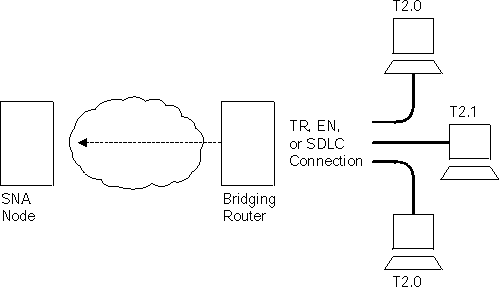
When using BAN, end stations function as if they are directly connected to an SNA node via a Token-Ring, Ethernet, or SDLC line as shown in Figure 20. Though their data actually passes through a 2210 and over a Frame Relay network, this is transparent to the end stations.
Figure 20. Direct Connection of End Stations to an SNA Node Using BAN

Designed to meet the needs of customers who do not require a full DLSw implementation, BAN provides an economical method for connecting to IBM environments. Offering a path to full DLSw capability, BAN provides three major benefits to customers who need to internetwork with the IBM environment:
| Note: | You can use a BAN DLCI for IP traffic. This allows you to manage the router (via SNMP) over the same DLCI you are using for SNA (via BAN). |
The BAN feature in the router works by filtering the frames sent by Type 2.0 or 2.1 end stations. Each BAN frame is modified by the router to comply with Bridged 802.5 (Token-Ring) Frame format. The router examines each frame, and allows only those with the BAN DLCI MAC address to pass over a DLCI to the mainframe. The destination MAC address in the bridged 802.5 frame is replaced with the Boundary Node Identifier in frames destined for the SNA node.
With BAN, only one DLCI ordinarily is needed. However, BAN may use many DLCI connections between the router and the IBM environment. In some cases, you may want to set up more than one DLCI to handle BAN traffic. See "Setting up Multiple DLCIs" for more information.
There are two ways to use the BAN feature:
The sections that follow explain how to configure each method.
You can implement BAN in two ways: straight bridging and DLSw terminated. With straight bridging, you configure BAN to bridge LLC2 frames from Type 2.0 or Type 2.1 end stations straight into the SNA node. With DLSw Terminated, BAN terminates the LLC2 connection at the router running DLSw. In this discussion, we refer to straight bridging as BAN Type 1 and DLSw Terminated as BAN Type 2.
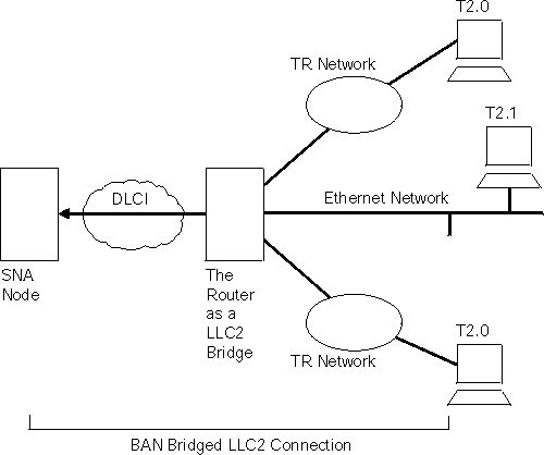
Figure 21 shows a BAN Type 1 (Bridged) connection. In this figure, notice that the router does not terminate the LLC2 traffic received from attached end stations. Instead, the router converts the frames it receives to Bridged Token-Ring format (RFC 1490/2427) frames, and bridges directly to the SNA node.
Figure 21. BAN Type 1: The Router as an LLC2 Bridge

In this case, the router acts as a bridge between the SNA node and the end stations. DLSw does not terminate LLC2 sessions at the router, as does BAN Type 2. End-station frames can be Token-Ring, or Ethernet format, provided the bridge is configured to support that type of frame.
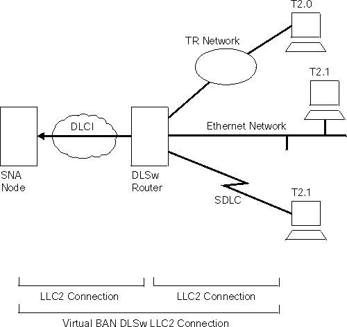
Figure 22 shows a BAN Type 2 (Virtual BAN DLSw) connection. In this figure, notice that the DLSw router does not function as a bridge. The router terminates the LLC2 traffic received from attached end stations. At the same time, the router establishes a new LLC2 connection to the SNA node over the Frame Relay network. Thus, though two LLC2 connections exist within the transaction, the break between them is transparent both to the SNA node and the end stations. The result is a virtual LLC2 connection between the SNA node and the end stations.
Figure 22. BAN Type 2: Local DLSw Conversion

The SDLC session is terminated in the router, and a separate LLC2 session exists between the router and the SNA node. The SDLC station appears to the SNA node as a Frame Relay attached station.
Remote DLSw is supported for both types of BAN. Either BAN Type 1 or Type 2 connections can be used by routers functioning as DLSw partners to connect Type 2.0 or 2.1 end stations to an SNA node.
Straight bridging of frames (BAN Type 1) is generally preferred because it provides fast delivery of data with minimal network overhead. However, there are exceptions. If usage on a DLCI is too high, session timeouts might occur in a bridged configuration. Conversely, session timeouts rarely occur in a DLSw configuration (BAN Type 2) since this type of configuration terminates and then recreates LLC2 sessions at the local (DLSw) router.
When you are configuring BAN, the system prompts you for information. Often, the system provides default values, which you accept by pressing Return.
To use the BAN feature, you must:
These steps are documented in the example that follows. The example assumes that you are setting up a single DLCI to carry BAN traffic. Depending on your circumstances and needs, you may want to set up multiple DLCIs for redundancy or for increased total bandwidth to the IBM environment. In this case, the BAN DLCI MAC address of the 2210 must be identical to the BAN DLCI MAC address of the ISDN backup 2210. Also, the value of the internal bridge segment of the 2210 must be different from the value of the internal bridge segment of the backup 2210. See "Setting up Multiple DLCIs" for more information.
To access the Frame Relay configuration prompt, type network interface# at the Config> prompt as shown in the following example. (Interface# is the number of the Frame Relay interface.)
Config>network 2
Frame Relay user configuration
FR Config>
At the FR Config> prompt, add a permanent circuit as shown in the following example. The router will prompt you for:
FR Config>add permanent
Circuit number  [16]? 20
Committed Information Rate in bps  [64000]?
Committed Burst Size(Bc) in bits (64000)?
Excess Burst Size (Be) in bits(0)?
Assign circuit name []? 20-ncp10
Is circuit required for interface operation [N]?
FR Config>
The DLCI you create becomes the PVC that connects the 2210 and the SNA node when BAN is used. The next step consists of configuring this PVC as a bridge port.
| Note: | If you want to set up multiple BAN DLCIs connected to the same or different SNA nodes, you must configure frame relay separately for each DLCI. See "Setting up Multiple DLCIs" for more information. |
Next, you must configure the PVC as a bridge port. To do this, use the protocol command at the Config> prompt as shown:
Config>protocol asrt
Adaptive Source Routing Transparent Bridge user configuration
ASRT config>
At the ASRT Config> prompt, add a port as shown. The router will prompt you for an interface number. The number you assign will be the FR interface number on the bridge. You will be prompted for a port number and a circuit number. The circuit number you assign must be the same as the number used when configuring the device for bridging over Frame Relay in Step 1.
ASRT config>add port
Interface Number [0]? 2
Port Number [5]?
Assign circuit number [16]? 20
ASRT config>
Next, enable source routing and define source-routing segment numbers for the Frame Relay port:
ASRT config>enable source routing
Port Number [3]? 5
Segment Number for the port in hex (1 - FFF) [1]? 456
Bridge Number in hex (1-9, A-F) [1]?
ASRT config>
Last, disable transparent bridging on the bridge port as shown:
ASRT config>disable transparent bridging
Port Number [3]? 5
ASRT config>
If BAN type 2 connections are being used, enable DLSw for bridging.
ASRT config>enable dls
ASRT config>
The next step consists of configuring the router for BAN.
You must configure the router for BAN from the ASRT config> prompt. The addition of a BAN port on the router will not be verified until you restart the router. Note that, as in steps 1 and 2, bridge port 5 is the port used throughout this step.
  Config>protocol asrt
  ASRT config>ban
  BAN (Boundary Access Node) configuration
  BAN config>
At the BAN config> prompt, add the port number (5) on which you want to enable the BAN feature. You will be prompted to enter a BAN DLCI MAC address and the Boundary Node Identifier address as shown:
  BAN config>add 5
  Enter the BAN DLCI MAC Address []? 400000000001
  Enter the Boundary Node Identifier MAC Address [4FFF00000000]?
In this example, 400000000001 is the MAC address of the DLCI. This is the address to which attached end stations will send data. (See Figure 21 and Figure 22). The other address, 4FFF00000000, is the default boundary node identifier address. To accept it, press Enter.
| Note: | The boundary node identifier corresponds to the destination MAC address placed in the bridged 802.5 frames sent from the 2210 to the SNA node. The default of 4FFF00000000 matches the default used by the IBM Network Control Program (NCP). The NCP address is specified in the NCP definition by the LOCADD keyword of the LINE statement that defines the physical Frame Relay port. For other SNA nodes that support bridged 802.5 frames over frame relay, the boundary node identifier must be set to the MAC address that the SNA node has configured for this virtual circuit. |
Specifying the BAN Connection Type: The next prompt asks you to specify which type of BAN connection you want to add: bridged or DLSw terminated. These two methods are described in preceding sections as BAN Type 1 and BAN Type 2. Type 1, straight bridging, is the default. You should accept the default unless you want inbound traffic to be terminated at the router.
After you enter b or t, the router informs you that the BAN port has been added.
  Do you want the traffic bridged (b) or DLSw terminated (t) (b/t) [b]?
  BAN port record added.
If BAN type 2 connections are being used, then DLSw must be configured. This involves enabling DLSw, setting the DLSw segment number, adding the local DLSw TCP partner, and opening the service access points (SAPs) associated with the FR interface and the LAN interface. If you fail to perform this DLSw configuration, you will not be able to use BAN type 2 (DLS terminated) connections.
Enable DLSw, using the enable dls command from the DLSw config> prompt.
Set the DLSw segment number using the set srb command form the DLSw config> prompt.
To add a local DLSw TCP partner, do the following at the DLSw config> prompt:
DLSw config>add tcp
Enter the DLSw neighbor IP Address [0.0.0.0.]? 128.185.236.33
Neighbor Priority (H/M/L) [M]?
DLSw config>
Open the SAPs from the DLSw config> prompt as shown in this example:
DLSw config>open
Interface # [0]?
Enter SAP in hex (range 0-ff) [0]? 4
DLSw config>
Issuing the open command for interface 0 opens the SAP on the LAN interface. Issue the same command to open the SAP on the FR interface. Note that in each case, you enter the number 4 to open a SAP.
DLSw config>open
Interface # [2]?    [open on the FR interface]
Enter SAP in hex (range 0-ff) [0]? 4
DLSw config>
While one DLCI is usually sufficient to handle BAN traffic to and from the IBM environment, setting up two or more DLCIs may prove useful in some circumstances.
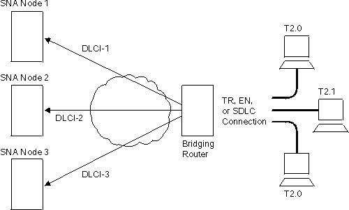
Redundant connections to multiple SNA nodes protect against a single SNA node failure. In addition, sharing BAN traffic among several DLCIs reduces the chance of one SNA node becoming overloaded. In a redundant DLCI configuration, PU Type 2.0 and 2.1 end stations can pass BAN traffic to different SNA nodes, as shown in Figure 23.
| Note: | Each DLCI is configured on a separate FR ASRT bridge port with the same DLCI MAC address. |
Figure 23. BAN Configuration with Multiple DLCIs to Different SNA Nodes

Multiple connections to the same SNA node increase the total bandwidth available for communicating with the IBM environment. This reduces the possibility of congestion on a single DLCI.
You may want to set up two or more DLCIs if you have a large amount of BAN traffic and another FR connection at your disposal. A second DLCI can provide greater total bandwidth to the SNA node, and protect you against unexpected failures.
Setting up multiple DLCIs is simple, particularly if you do this during the initial BAN configuration. When setting up multiple connections, remember that each Frame Relay DLCI corresponds to a specific SNA node in the IBM environment. To pass BAN frames to that SNA node, you must specify the correct circuit number when establishing the Frame Relay connection. Your frame relay provider can give you the circuit number for each of your connections.
To set up DLCI connections to different SNA nodes ( "Scenario 1: Setting up a Fault-Tolerant BAN Connection"), you must:
To set up a second DLCI connection to the same SNA node (see "Scenario 2: Increasing Bandwidth to the IBM Environment") follow the same steps. In "Scenario 2: Increasing Bandwidth to the IBM Environment", the circuit number provided for the second Frame Relay port will differ from the first. However, each circuit number identifies a different DLCI and a distinct path to the IBM environment.
When you restart the router, the router will validate that the BAN bridge port is a Frame Relay bridge port with source-routing behavior. You should check the BAN configuration with the list command as shown here:
  BAN config>list

  bridge    BAN                  Boundary               bridged or
  port      DLCI MAC Address     Node Identifier        DLSw terminated
  ------    ----------------     ---------------        ---------------
  5         40:00:00:00:00:01    4F:FF:00:00:00:00      bridged

  BAN config>
As this example shows, the list command displays each aspect of the BAN configuration, giving the bridge port (5 in this case), the MAC address of the DLCI and the boundary node identifier for the SNA node, and whether the port is bridged or DLSw terminated.
To verify that BAN has initialized properly on startup, you can use GWCON as follows:
  + protocol asrt
  ASRT>ban
  BAN (Boundary Access Node) console

  BAN>list
  bridge  BAN                Boundary           bridged or
  port    DLCI MAC Address   Node Identifier    DLSw terminated   Status
  ----    ----------------   ---------------    ---------------   -------
  5       40:00:00:00:00:01  4F:FF:00:00:00:00  bridged           Init Fail

  BAN>
GWCON provides three status messages:
If you receive a status other than Up, you should check the router's ELS messages to diagnose the problem. "Enabling Event Logging System (ELS) Messages for BAN" explains how to enable ELS messages.
After initial BAN configuration and restart, it is a good idea to enable ELS messages to see whether the configuration is working as planned. You can enable BAN-specific messages from the Config> prompt as shown:
  Config>ev
  Event Logging System user configuration
  ELS config>display subsystem ban all
  ELS config>
Entering this command displays all BAN subsystem messages. This will cause ELS to notify you of all BAN-related behavior. After running BAN for a while, you may want to turn off some messages. You can turn off specific ELS BAN messages by using the nodisplay command and the specific message number. This example illustrates how to turn off the ban.9 message:
ELS config>nodisplay event ban.9
For a list and explanation of all BAN-related messages, refer to the Event Logging System Messages Guide.