
This chapter describes the voice adapter and its use with the Nuera F200 Frame Relay Access Device (FRAD). The majority of the dialing plan and configuration is done on the F200. The F200 handles all the connections between the 2212 ports. The 2212 port configuration includes only enough information to reach the F200.
This chapter includes the following sections:
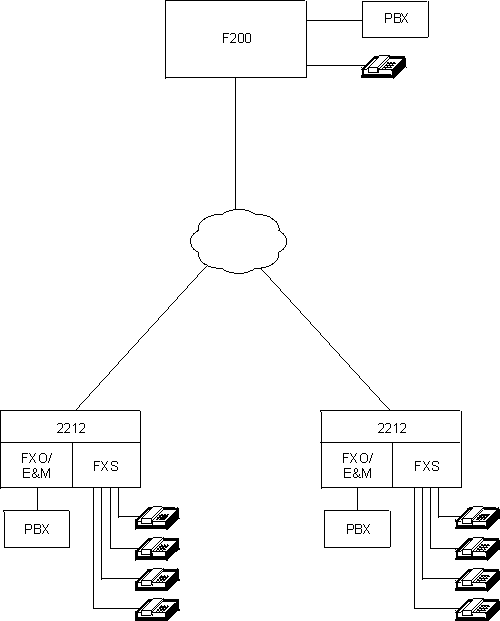
Figure 50 shows a network where two 2212s are connected to a Nuera F200 FRAD. Each 2212 can contain up to four voice adapter cards with each card containing two voice ports for a total of eight ports. The ports can have FXS, FXO, or E&M interfaces. Each voice port can attach directly to a private branch exchange (PBX), another telephone, or a key system. Each voice port can support Frame Relay connections to a maximum of eight F200s. Voice ports can also connect to other voice ports within the same 2212. This is called local call routing.
Figure 50. Nuera F200 to 2212 Voice Port Communication
 |
Defining the voice adapter is a two-step configuration process. First you need to define the F200 to communicate with the 2212 voice port and then similarly define the 2212 voice port to communicate with the F200.
For examples of defining call-processing, dial-matching, network-output, and telco-output rules, see Configuring and Monitoring Voice Adapters.
To configure the F200 to communicate with a 2212 voice adapter, you need to define a set of parameters called a dialing plan. An F200 dialing plan contains the following information:
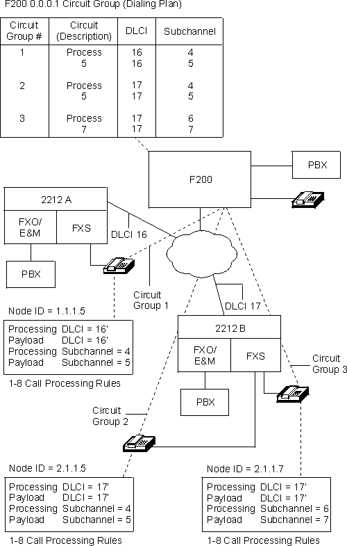
Figure 51 shows the routing information needed for communication between voice ports on 2212A and 2212B.
Figure 51. Configuring Voice Port Call Processing Information
 |
An F200 circuit group defines a virtual voice network trunk between an F200 and a remote node. Although an F200-F200 circuit group can contain many individual circuits, an F200-2212 voice adapter circuit group only contains one (PVC) circuit. The circuit group connects to the remote node (F200 or 2212 voice port). In Figure 51, Circuit Group 1 connects to the 2212A voice port having a node ID of 1.1.1.5. Circuit Group 2 connects to the 2212B voice port having a node ID of 2.1.1.5. Circuit Group 3 connects to the 2212B voice port having a node ID of 2.1.1.7. Each 2212 voice port, even ports on the same 2212, must have a unique node ID. Therefore a unique circuit group must be defined to the F200 for each 2212 voice port.
An F200 circuit descriptor defines the individual circuits within each circuit group. For an F200-F200 circuit group, you can have multiple circuit descriptors; one for each circuit in the group. Because an F200-2212 voice adapter circuit group only contains one circuit, an F200-2212 voice adapter circuit group only contains one circuit descriptor.
Circuit descriptors contain both processing circuit and payload circuit information. The processing circuit is used to transfer packets required to establish the call and terminate the call. These packets are Nuera's proprietary CALL SETUP, CONNECT, ANSWER, and RELEASE packets. The payload circuit is used to transfer packets containing the actual compressed voice data.
In Figure 51, the F200 has a dialing plan that contains three circuit groups, one for each 2212 voice port. When an F200 receives a request to establish communication with a specific node ID, it uses the circuit group to locate the target device. An F200 circuit group contains the following information:
| Note: | When defining a circuit descriptor for an F200-2212 voice adapter circuit, the circuit descriptor and the payload subchannel number must match. The minimum subchannel value you can specify is 4. All the circuit groups between an F200 and a 2212 can use the same DLCI. |
A dialing plan for an F200 consists of from 1 to 4 translation rules. These rules control how devices connect and communicate with the F200. Each translation rule consists of a number of ordered cases (from 1 to 100). Each F200 circuit group is associated with a specific translation rule. Each translation rule is composed of the following elements:
During call setup, the source and destination numbers are compared to the corresponding match rules in each translation rule case. The comparisons are made in ascending order until a match is found. When a match is found, the route rule in the matched case routes the call. The output rule in the matched case modifies the call setup information or generate dial digits.
To configure a 2212 voice port to communicate with an F200, you need to define the following rules:
For each 2212, you can define up to eight telco output rules -- one rule for each voice port. Telco output rules determine how dial digits are transmitted on the telco interface. Each telco rule is comprised of a combination of destination dial digits, source number digits, constants, and pauses.
For each voice port, you can define up to eight call processing rules. Each rule contains a set of connection parameters that determine how a connection is established. Each call processing rule contains the following information:
| Note: | The payload and processing parameters defined for a voice port should correspond to the payload and processing parameters defined for F200s that can be connected to the voice port. |
The dial digit matching rule lets you specify the range of acceptable digits at each position in a dial digit sequence. You can specify multi-digit wildcards as well as a sequence that causes an immediate connection during an "off-hook" condition. You can define a pool of up to 64 rules and specify a dial digit rule in each call processing rule.
The network output rule lets you specify how the destination number should appear in the call setup Frame Relay packet. This rule consists of a combination of destination number digits and constants.
When a 2212 voice port originates a call, the destination number is compared to that port's dial digit matching rules. These rules are defined in the call processing rules for that port. When a match is found, the DLCI and subchannel from the matching call processing rule determine the destination node. If the destination number needs to modified, the network output rule determines how it should be modified.
When a 2212 receives a call, the DLCI and subchannel pair determines which voice port is to receive the call. Each voice port accepts calls from any DLCI and subchannel pair that is defined in one of its call processing rules. The destination voice port's telco output rule is used with the destination number to generate the dial digit outpulse sequence, if one is required.
If you only require a limited network accessibility, you can communicate between two voice ports without using a Nuera F200 by using the following methods:
By defining corresponding call processing rules for each voice port, calls can be made between two voice ports in different 2212s without using an F200. Each of these rules must specify the same payload and call processing subchannels, as well as corresponding payload and call processing DLCIs. When communicating without an F200, the node ID field is not used.
| Note: | Without connecting to an F200, each voice port can connect to a maximum of eight remote voice ports. If you enable local call routing on a voice port, that port can only connect to seven remote voice ports. |
Calls can be made between two voice ports on the same 2212 without using an F200. You can do this by configuring one of the eight call processing rules on each port for local call routing. Local call routing compares the destination number to the local number configured for each voice port that has a local call rule defined. You can specify the number of leading digits to be compared in each port's local number.
The network output rule, specified in a local route call rule, must specify enough destination number digits to correctly route the call.
Because the source voice ports and the destination voice ports are within the same 2212, a local routing call rule does not contain DLCI information or subchannel information.