 Wave
quantities
Wave
quantitiesThe Wave Quantities submenu selects a wave quantity to be measured and displayed.

a1 Src Port 1, b1 Src Port 1, b2 Src Port 1, a2 Src Port 2, b1 Src Port 2 and b2 Src Port 2 select the standard 2-port wave quantities a1, b1, a2, and b2, to be measured in forward or reverse direction with port 1 or 2 providing the stimulus signal.
More Wave Quantities opens a dialog to define and select arbitrary wave quantities for different source ports or higher port numbers.
In contrast to S-parameters, wave quantities are not system error corrected. A power calibration can be applied to wave quantities; see Data Flow.
Select the standard 2-port wave quantities a1, a2, b1, and b2 for different source ports:
The predefined wave quantities are obtained with different source ports. a1 Src Port 1, b1 Src Port 1 and b1 Src Port 2 are measured at Port 1 of the analyzer. a2 Src Port 2, b2 Src Port 1 and b2 Src Port 2 are measured at Port 2 of the analyzer.
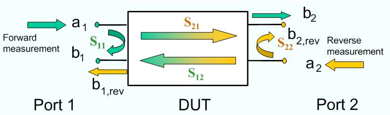
a1 Src Port 1 is the wave transmitted at test port 1. In a standard S-parameter measurement, this wave is fed to the input port (port 1) of the DUT (forward measurement).
b1 Src Port 1 is the wave received at test port 1. In a standard S-parameter measurement, this is the reflected wave at port 1 of the DUT (forward measurement).
b2 Src Port 1 is the wave received at test port 2. In a standard S-parameter measurement, this wave is transmitted at port 2 of the DUT (forward measurement).
a2 Src Port 2 is the wave transmitted at test port 2. In a standard S-parameter measurement, this wave is fed to the output port (port 2) of the DUT (reverse measurement).
b1 Src Port 2 is the wave received at test port 1. In a standard S-parameter measurement, this wave is transmitted at port 2 of the DUT (reverse measurement).
b2 Src Port 2 is the wave received at test port 2. In a standard S-parameter measurement, this wave is fed to the output port (port 2) of the DUT (reverse measurement).
The analyzer can also measure wave quantities for other source ports; see More Wave Quantities.
|
Remote control: |
CALCulate<Ch>:PARameter:MEASure
"<Trace_Name>", "A1"
| ... Create
new trace and select name and measurement parameter: |
Opens a dialog to define and select arbitrary wave quantities for different source ports or higher port numbers.

The notation for wave quantities and the functionality of the More Wave Quantities dialog is analogous to the definition of S-parameters.
Wave Quantity selects the type (left pull-down list) and the port number assignment (right pull-down list) of the wave quantity.
Show as selects the physical unit of the displayed trace. It is possible to display the measured Voltage V or convert the wave quantity into an effective power according to P = V2/Re(Z0). Z0 denotes the reference impedance of the source port (for wave quantities an) or of the receive port (for wave quantities bn). The reference impedances are defined in the Port Configuration dialog. This function is also available for memory traces where the remaining control elements of the dialog are grayed.
Source Port contains all analyzer ports or external generators which can be used as a source for the stimulus signal. The list contains all analyzer ports Port 1 to Port n. Generators (Gen 1, Gen 2, ...) must be configured explicitly in the System Configuration – External Generators dialog before they appear in the list. The analyzer places no restriction on the combination of source ports and port numbers of the measured wave quantity, so it is even possible to measure a2 while the source port is port 1 (e.g. in order to estimate the directivity of the coupler in the internal test set).
The measurement process for external generators Gen 1, Gen2... in the Source Port list differs from the measurement process for internal source ports:
An external generator always represents a permanent signal source that is switched on for all partial measurements. In contrast, an analyzer port is switched off for partial measurements that do not require a source signal.
The external source is measured in the first partial measurement where an internal source is active. This means that no separate partial measurement for the external generator signal is needed. If no internal source is needed at all, the external source is measured in the first partial measurement.
|
Remote control: |
CALCulate<Ch>:PARameter:MEASure
"<Trace_Name>", "A1" | ... Create
new trace and select name and measurement parameter: |
