A network analyzer which is equipped with option R&S ZVAB-K14, Universal Interface, can interact with an external part handler. The digital control signals on the interface connector indicate the possible start and the end of a measurement, as well as a global limit check result. Typically, the handler will insert the device to be tested into a test fixture, provide a trigger pulse to initiate the measurement, remove and replace the device after the measurement is complete and sort it into pass/fail bins. A sample flow diagram for this process is shown below.
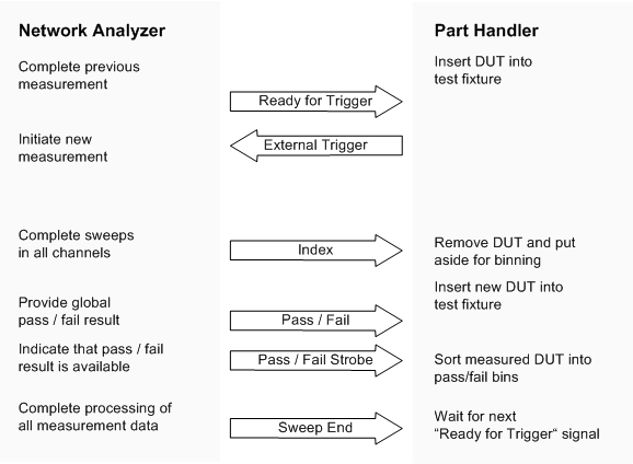
Possible stages of an automated test
 Preparation
of the network analyzer and the part handler
The network analyzer configuration depends on the measurement to be made. Starting from the preset state, you will usually have to adjust the following settings:
Enable external trigger: Channel – Sweep – Trigger – External
Select single sweep mode: Channel – Sweep – Single(All Chans)
Define limit lines and enable the limit check: Trace – Lines – Define Limit Line....
The Universal Interface connector must be connected to the part handler using an appropriate cable. If required, configure the data ports to ensure that the network analyzer and the part handler are compatible.
Most of the signals in the figure below are controlled by the measurement. It is possible though to configure the Output 1 and Output 2 signals and to route the Index and Ready for Trigger signals using SCPI commands.
The CONTrol:HANDler:OUTPut<port>... commands set the output signals to a definite initial state and specify whether this state will change when the Input 1 signal changes to "Low". This mechanism provides either static output signals or output signals which are controlled by Input 1.
The Index and Ready for Trigger signals can be routed to pins 20 and 21 of the Universal Interface connector, where they replace the PORT B6 and PORT B7 input/output signals. See section Data Ports.
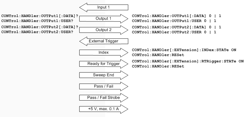
Control signals and power supply
|
Remote control: |
In addition to the control signals, the Universal Interface provides four bi-directional data ports A, B, C, D. The data ports must be configured explicitly using SCPI commands; they are not controlled by the measurement.
With an output data port you can configure the part handler or other devices used in testing from the network analyzer.
With an input data port you can configure the network analyzer using external signals and an appropriate control program.
Device configurations via data port signals are usually performed in a preliminary stage, prior to the actual measurement sequence. If the Index and Ready for Trigger signals are enabled at this stage (see section Control Signals), they replace the PORT B6 and PORT B7 signals. Port B can still be used as a 6-bit parallel input/output port.
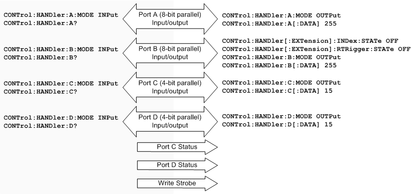
Data ports and related signals
|
Remote control: |
Option R&S ZVAB-K14, Universal Interface, must be installed by an R&S service representative. The option includes a Centronics 36 input/output connector which is placed in the top left panel of the rear panel. The pin assignment of the connector is shown below. A slash (/) at the beginning of the signal name indicates that it is an active low (negative logic) signal.
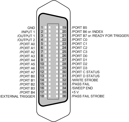
Pin assignment of the Universal Interface connector
The input and output signals at the connector are described below.
|
Pin No. |
Signal |
Input
(I) or |
Function |
|
1 |
GND |
– |
Ground |
|
2 |
/INPUT 1 |
I |
When a negative pulse is fed to this port, the /OUTPUT 1 and /OUTPUT 2 signals (pins no. 3 and 4) change to "Low". |
|
3 |
/OUTPUT 1 |
O |
Changes to "Low" when the /INPUT 1 (pin no. 2) receives a negative pulse. |
|
4 |
/OUTPUT 2 |
O |
Changes to "Low" when the /INPUT 1 (pin no. 2) receives a negative pulse. |
|
5 |
/PORT A0 |
I or O |
Port A, bit no. 0 (8-bit parallel input or output port) |
|
6 |
/PORT A1 |
I or O |
Port A, bit no. 1 |
|
7 |
/PORT A2 |
I or O |
Port A, bit no. 2 |
|
8 |
/PORT A3 |
I or O |
Port A, bit no. 3 |
|
9 |
/PORT A4 |
I or O |
Port A, bit no. 4 |
|
10 |
/PORT A5 |
I or O |
Port A, bit no. 5 |
|
11 |
/PORT A6 |
I or O |
Port A, bit no. 6 |
|
12 |
/PORT A7 |
I or O |
Port A, bit no. 7 |
|
13 |
/PORT B0 |
I or O |
Port B, bit no. 0 (8-bit parallel input or output port) |
|
14 |
/PORT B1 |
I or O |
Port B, bit no. 1 |
|
15 |
/PORT B2 |
I or O |
Port B, bit no. 2 |
|
16 |
/PORT B3 |
I or O |
Port B, bit no. 3 |
|
17 |
/PORT B4 |
I or O |
Port B, bit no. 4 |
|
18 |
/EXTERNAL TRIGGER |
I |
External trigger signal |
|
19 |
/PORT B5 |
I or O |
Port B, bit no. 5 |
|
20 |
/PORT B6 or |
I or O |
Port B, bit no. 6 |
|
21 |
/PORT B7 or |
I or O |
Port B, bit no. 7 |
|
22 |
/PORT C0 |
I or O |
Port C, bit no. 0 (4-bit parallel input or output port) |
|
23 |
/PORT C1 |
I or O |
Port C, bit no. 1 |
|
24 |
/PORT C2 |
I or O |
Port C, bit no. 2 |
|
25 |
/PORT C3 |
I or O |
Port C, bit no. 3 |
|
26 |
/PORT D0 |
I or O |
Port D, bit no. 0 (4-bit parallel input or output port) |
|
27 |
/PORT D1 |
I or O |
Port D, bit no. 1 |
|
28 |
/PORT D2 |
I or O |
Port D, bit no. 2 |
|
29 |
/PORT D3 |
I or O |
Port D, bit no. 3 |
|
30 |
/PORT C STATUS |
O |
Indicates the status of port C: |
|
31 |
/PORT D STATUS |
O |
Indicates the status of port D: |
|
32 |
/WRITE STROBE |
O |
Changes to "Low" when valid data is present at any of the output ports (i.e. when the output level at any port changes). |
|
33 |
/PASS FAIL |
O |
Indicates the status of the global
limit check for the last measurement: |
|
34 |
/SWEEP END |
O |
Indicates the end of the measurement. Changes to "Low" after all sweeps in all channels have been completed and the measurement data has been processed. |
|
35 |
+5 V DC |
O |
DC power supply for external devices; +5 V ± 250 mV, max. 0.1 A |
|
36 |
/PASS FAIL STROBE |
O |
Changes to "Low" when limit check results are present on /PASS FAIL (pin no. 33). |
All digital input signals must be TTL compatible with an allowed input voltage range between –0.5 V and +5.5 V. The circuit diagram of the input path is shown below.
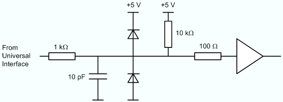
Circuit diagram of the input path
Digital output signals are low-voltage TTL compatible with output voltages between 0 V and +3.3 V. The circuit diagram of the output path is shown below.
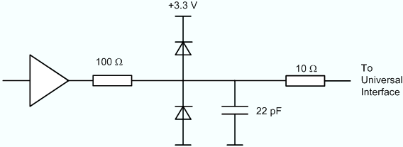
Circuit diagram of the output path
The default configuration of the signals is listed below. Notice that *RST or Preset do not change the configuration of the Universal Interface. Use CONTrol:HANDler:RESet to restore default values.
|
Signal |
*RST Configuration |
|
Port A, Port B |
Output ports, all bits "High" (decimal 0) |
|
Port C, Port D |
Input ports |
|
/PORT C STATUS, /PORT D STATUS |
"Low" |
|
/OUTPUT 1, /OUTPUT 2 |
"High" |
|
/SWEEP END |
"High" |
|
/PASS_FAIL |
"High" |
|
Remote control: |
CONTrol:HANDler:RESet (resets all configurable signals) |
The timing of the essential measurement control signals is shown in the figure below. The duration of the shaded time intervals depends on the measurement settings.
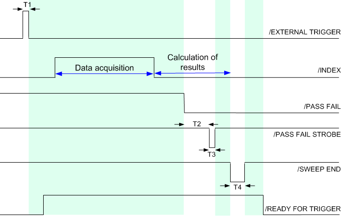
Timing of measurement control signals
The figure above contains the following pulse durations and response times.
|
Time |
Description |
Value |
|
T1 |
Pulse duration of /EXTERNAL TRIGGER |
Minimum value: 1 μs |
|
T2 |
Response time of /PASS FAIL STROBE |
25 μs |
|
T3 |
Pulse duration of /PASS FAIL STROBE |
1 μs |
|
T4 |
Pulse duration of /SWEEP END |
12 μs |
The timing of the data port signals and the input/output signals is as follows:
The low pulse of the /WRITE STROBE signal occurs approx. 0.2 μs after a value is written to the output ports A to D. The pulse duration of the /WRITE STROBE signal is 1 μs.
The low pulse of the /OUTPUT 1 or /OUTPUT 2 signals (if enabled) occur approx. 0.6 μs after the falling edge of the /INPUT 1 signal. The pulse duration of the /OUTPUT 1 and /OUTPUT 2 signals is 1 μs.