The following example outlines the essential steps for a noise figure measurement. The measurement comprises the following stages:
An attenuator between the NWA source port and the DUT input limits the source power.
A pre-amplifier between the DUT output and the NWA receive port can reduce the noise figure of the NWA receiver.
 The Noise
Figure Setup Guide guides you through the measurement procedure
outlined below. All required settings and dialogs are accessible from
the setup guide.
The Noise
Figure Setup Guide guides you through the measurement procedure
outlined below. All required settings and dialogs are accessible from
the setup guide.
Test setup for noise figure measurement
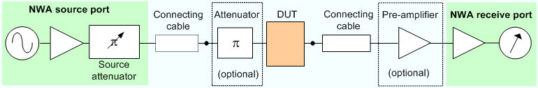
We assume that Port 1 is used as the NWA source port, Port 2 is used as the receive port. Generalization to other port assignments or to test setups without external attenuator and/or pre-amplifier is self-explanatory.
Reset the analyzer to ensure that the basic operating mode is set: Sweep Type: Lin. Frequency, Trace - Measure: S21, Trace - Format: dB Mag.
Adjust the sweep range to your DUT, e.g. Channel - Stimulus - Start: 1GHz, Stop: 6 GHz.
Open the Channel - Mode - Noise Figure Meas menu and select Define Noise Figure Measurement.
Keep the default settings for measurement time and mode; click OK to activate the noise figure measurement.
After activating the measurement, the Noise Figure Calibration function is available.
Calibration involves several stages. The first stage is a regular power calibration of the NWA source and receiver.
Connect an external power meter to the end of the cable between the NWA source port (port 1) and the attenuator input.
Select Channel - Calibration - Start Power Cal - Source Power Cal and calibrate the port 1 source power in the usual way. Ensure that the calibrated source power will not overdrive the pre-amplifier / NWA receiver system.
Remove the external power sensor and close the connection between port 1 and port2.
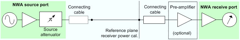
Select Channel - Calibration - Start Power Cal - Receiver Power Cal and calibrate the port 2 receiver power (wave quantity b2) in the usual way. For high input powers at the NWA receive port, it is recommended to set the IF Gain b to Low Distortion (Channel - Mode - Port Configuration). Make sure that the power calibration is applied to the active channel.
The power calibration is complemented by a Noise Figure Calibration.
Select Channel - Mode - Noise Figure Meas - Noise Figure Cal to open the calibration wizard.
Perform the three calibration steps as described in section Noise Figure Calibration. Make sure that the calibration is applied to the active channel.
An S-parameter calibration is required for S-parameter measurements in parallel to the noise figure measurement. You can choose between a one path two port and a full two port calibration for the analyzer ports 1 and 2. It is recommended to select the AVG detector in the calibration wizard.
Perform a manual or automatic calibration for your test setup as outlined in the Calibration example.
The default trace shows the forward transmission coefficient S21, which is a measure of the gain, if the measured DUT is an amplifier. For a wide class of test setups the noise figure of the DUT can be measured and displayed in parallel to the S-parameters.
Establish the measurement test setup, connecting the external attenuator and the DUT as shown above (see Test setup for noise measurement).
Select Trace - Trace Select - Add Trace + Diag Area to create a new trace Trc2.
Select Trace - Measure - Noise Figure. In the dialog opened, ensure matching port assignments (Dut Input: Port 1, Dut Output: Port 2) and click OK.
The new trace Trc2 shows the noise figure of the DUT. You do not have to repeat any of the preliminary steps (activation, calibration ...) if you wish to measure several DUTs using the same channel settings.
The figure below shows the noise figure and gain of a 3 dB amplifier. For convenience, the two traces Trc1 and Trc2 were renamed Noise_Figure and Gain, respectively. The second trace was assigned to a second channel.