Opens a submenu to search for trace segments with a bandpass or bandstop shape and determines characteristic filter parameters.
 Bandfilter
search and filter parameters
Bandfilter
search and filter parameters
Bandpass and bandstop regions can be described with the same parameter set:
A bandpass region contains a local maximum around which the magnitude of the trace falls off by more than a specified x dB Bandwidth.
A bandstop region contains a local minimum around which the magnitude of the trace increases by more than a specified x dB Bandwidth.
The analyzer locates bandpass and bandstop regions and determines their position (Center frequency) and shape (Bandwidth, LBE, UBE, Quality factor Q; see Show Results). For a meaningful definition of the x dB Bandwidth criterion, the trace format must be dB Mag.
Bandpass Search Ref to Max activates the search for a bandpass region in the active trace.
Bandpass Search Ref to Marker activates the search for a bandpass region in the active trace, starting at the position of the active marker.
Bandstop Search Ref to Max activates the search for a bandstop region in the active trace.
Bandfilter Tracking causes the bandfilter search to be repeated after each sweep.
x dB Bandwidth... sets the level defining the filter bandwidth.
Search Range... confines the search to a subrange of the sweep.
Search Markers and Result Off hides the markers and bandfilter parameters in the diagram area.
 Bandfilter
mode can be selected for a broad range of measured quantities (Trace
– Measure),
provided that the display format is dB Mag.
To obtain real filter parameters, the measured quantity must be a transmission
S-parameter and a frequency sweep must be performed. For other quantities
(e.g reflection parameters), the Bandfilter
functions are still useful to analyze general trace properties.
In some display formats (e.g. Phase)
the bandfilter search is disabled.
Bandfilter
mode can be selected for a broad range of measured quantities (Trace
– Measure),
provided that the display format is dB Mag.
To obtain real filter parameters, the measured quantity must be a transmission
S-parameter and a frequency sweep must be performed. For other quantities
(e.g reflection parameters), the Bandfilter
functions are still useful to analyze general trace properties.
In some display formats (e.g. Phase)
the bandfilter search is disabled.
Activates the search for a bandpass region on the active trace and activates bandfilter Tracking. A bandpass region is the tallest peak in the search range with a minimum excursion specified by means of the x dB Bandwidth parameter.
When Bandpass Search is activated the analyzer uses (or creates) the four markers M 1 to M 4 to locate the bandpass region.
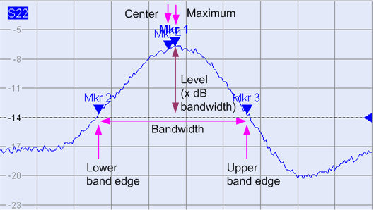
M 1 indicates the maximum of the peak (Max).
M 2 indicates the point on the left edge of the peak where the trace value is equal to the maximum minus x dB Bandwidth (Lower Band Edge, LBE).
M 3 indicates the point on the right edge of the peak where the trace value is equal to the maximum minus x dB Bandwidth (Upper Band Edge, UBE).
M 4 indicates the center of the peak, calculated as the geometric mean value of the LBE and UBE positions: fCenter = sqrt (fLBE * fUBE).
The bandfilter search results are displayed in the bandfilter info field.
 To search for a bandpass region in the vicinity of the
active marker, use Bandpass
Search Ref to Marker.
To search for a bandpass region in the vicinity of the
active marker, use Bandpass
Search Ref to Marker.
|
Remote control: |
CALCulate<Chn>:MARKer<Mk>:FUNCtion:BWIDth:MODE
BPASs |
Activates the search for a bandpass region on the active trace in the vicinity of the active marker and activates bandfilter Tracking. The bandpass region is the frequency range between the lower and the upper band edge; the band edges are defined by the magnitude of the trace at the marker position minus the x dB Bandwidth parameter:
In contrast to a Bandpass Search Ref to Max, the Bandpass Search Ref to Marker does not change the position of the active markers. The Loss is the response value at the marker position; the bandfilter search results are displayed in the bandfilter info field. The Lower Band Edge and the Upper Band Edge must fall into the search range, otherwise the bandfilter search results are invalid.
 Bandpass Search Ref
to Marker is particularly suitable for bandfilters with known center
frequency, with the active marker placed onto this center frequency. You can also use a peak search to
place the active marker on the maximum of the trace. Notice that, if the
active marker is off the peak, both band edges are more than x dB below
the peak response value.
Bandpass Search Ref
to Marker is particularly suitable for bandfilters with known center
frequency, with the active marker placed onto this center frequency. You can also use a peak search to
place the active marker on the maximum of the trace. Notice that, if the
active marker is off the peak, both band edges are more than x dB below
the peak response value.
To search for a bandstop region in the vicinity of the active marker, use
Bandfilter
Tracking
– Bandstop
Search Ref to Marker.
|
Remote control: |
CALCulate<Chn>:MARKer<Mk>:FUNCtion:BWIDth:MODE
BPRMarker | BSRMarker
|
Activates the search for a bandstop region on the active trace and activates bandfilter Tracking. A bandstop region is the lowest peak (local minimum) in the search range, provided that its level is at least <x dB Bandwidth> below the maximum (passband value).
When Bandstop Search is activated the analyzer uses (or creates) the four markers M 1 to M 4 to locate the bandstop region.

M 1 indicates the minimum of the peak (Min).
M 2 indicates the point on the left edge of the peak where the trace value is equal to the maximum in the search range (passband value) minus x dB Bandwidth (Lower Band Edge, LBE).
M 3 indicates the point on the right edge of the peak where the trace value is equal to the maximum in the search range (passband value) minus x dB Bandwidth (Upper Band Edge, UBE).
M 4 indicates the center of the peak, calculated as the geometric mean value of the LBE and UBE positions: fCenter = sqrt (fLBE * fUBE).
The bandfilter search results are displayed in the bandfilter info field.
To search for a bandpass region in the vicinity of the
active marker, use Bandpass
Search Ref to Marker.
Use Bandfilter
Tracking
to select other search modes.
|
Remote control: |
CALCulate<Chn>:MARKer<Mk>:FUNCtion:BWIDth:MODE
BSTOP |
Causes the bandfilter search to be repeated after each sweep: When tracking mode is active the markers typically change their horizontal and their vertical positions as the measurement goes on.
Tracking for the different bandfilter search modes is enabled or disabled in a selection box. Selecting a search mode for tracking also activates this mode.
![]()
The search modes have the following effect:
Bandpass Ref to Max / Bandstop Ref to Max: The bandpass / bandstop is the tallest / lowest peak in the search range.
Bandpass / Bandstop Ref to Marker: The bandpass / bandstop is the peak in the vicinity of the active marker position. The response values for the lower and upper band edges are calculated as the response values at the active marker position plus / minus x dB, where x is equal to the <x dB Bandwidth>. To be valid the peak must be above / below the response value for the band edges, and the band edges must fall into the search range.
Bandpass / Bandstop Absolute Level: The bandpass / bandstop is the tallest/lowest peak in the search range. To be valid, the peak must be above / below –x dB, where x is numerically equal to the <x dB Bandwidth> value. The Lower Band Edge and Upper Band Edge values are given by the frequencies where the trace is equal to –x dB.
Tracking is a toggle function: Selecting the function repeatedly switches the tracking mode on and off.
|
Remote control: |
CALCulate<Chn>:MARKer<Mk>:FUNCtion:BWIDth:MODE
|
Opens the numeric entry bar for the minimum excursion of the bandpass and bandstop peaks.

A bandpass peak must fall off on both sides by the specified x dB Bandwidth to be considered a valid peak.
A bandstop peak must be x dB Bandwidth below the maximum level in the search range (bandpass value) to be considered a valid peak.
|
Remote control: |
Opens the Search Range Dialog to confine the bandfilter search to a subrange of the sweep.
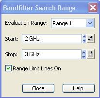
It is possible to define and store up to ten different search ranges for each trace. The bandfilter search is performed using the markers M 1, ..., M 4, irrespective of the selected search range.
The ten search ranges are valid for the entire setup. Each of them can be assigned to any marker in the setup, irrespective of the trace and channel that the marker belongs to.
The default search range of any new marker is Full Span. The analyzer provides greatest flexibility in defining search ranges. In particular, two search ranges may overlap or even be identical. The search is confined to the part of the search range that belongs to the sweep range.
The following example shows how search ranges can be used to search a trace for several bandpass regions.
|
Remote control: |
CALCulate<Chn>:MARKer<Mk>:FUNCtion:DOMain:USER |
Hides the info field with the results of a bandpass or a bandstop search and disables bandfiter tracking. The info field is displayed again (and tracking is re-enabled) when a new bandfilter search is performed.
The analyzer provides an alternative, short version of
the bandfilter info field; see System
– System
Config... –
General.
For a Bandpass/Bandstop Ref to Marker search, the info field contains the following search results:
Bandwidth is the n-dB bandwidth of the bandpass/bandstop region, where n is the selected x dB Bandwidth. The bandwidth is equal to the difference between the Upper Bandwidth Edge (UBE) and the Lower Bandwidth Edge (LBE).
Center is calculated as the geometric mean value of the LBE and UBE positions: fCenter = sqrt (fLBE * fUBE). If desired, the center frequency can be calculated as the arithmetic mean value fCenter = (fLBE + fUBE)/2; see System – System Config... –General.
Lower Band Edge is the closest frequency below the center frequency where the trace is equal to the center value minus n dB.
Upper Band Edge is the closest frequency above the center frequency where the trace is equal to the center value minus n dB.
The Quality Factor is the ratio between the Center frequency and the 3-dB Bandwidth; it does not depend on the selected x dB Bandwidth.
Loss
is the loss of the filter at its center frequency and is equal
to the response value of marker no. 4. For an ideal bandpass filter the
loss is zero (0 dB), for an ideal bandstop filter it is – dB.
dB.
For a Bandpass/Bandstop Ref to Marker search, the following modified definitions apply:
Lower Band Edge is the closest frequency below the active marker position where the trace is equal to the marker response value minus n dB.
Upper Band Edge is the closest frequency above the active marker position where the trace is equal to the marker response value minus n dB.
Loss is the response value of the active marker.
For a Bandpass/Bandstop Absolute Level search, the following modified definitions apply (x denotes the <x dB Bandwidth> value):
Lower Band Edge is the closest frequency below the peak frequency where the trace is equal to –x dB.
Upper Band Edge is the closest frequency above the peak frequency where the trace is equal to –x dB.
|
Remote control: |
CALCulate<Chn>:MARKer<Mk>:BWIDth? |
