In combination with an extension unit R&S ZVAX24, the R&S ZVA vector analyzer can create a pulsed RF signal and perform pulse profile measurements. Other R&S ZVAX measurements involve similar measurement stages.
The pulse profile measurement can be carried out with the following equipment:
Network analyzer (NWA) R&S ZVA24 with a firmware version V2.60 or higher and a motherboard ID number 1305.6470.02 (see "Info > Hardware Info ...")
Option R&S ZVA-K27, "Pulse Generator"
Option R&S ZVA-K7, "Pulsed Measurements"
Option R&S ZVA<n>-B16, "Direct Generator/Receiver Access" at source port 1
One R&S ZVAX24 extension unit equipped with option R&S ZVAX24-B271, "Pulse Modulator Port 1"
The pulse modulator option R&S ZVAX24-B271 provides a pulsed source signal at the NWA port 1. Pulse width and period are determined by the used pulse generator, which can e.g. be the internal pulse generator of the NWA provided by option R&S ZVA-B27. This option also provides a second "Sync" signal that can be used to synchronize the measurement to the rising edge of the generated pulses.
The DUT is connected between the test ports 1 and 2 of the analyzer; the transmitted pulsed signal is measured at port 2 using the analyzer's "Pulse Profile" mode.
The measurement involves the following steps:
Connection of the extension unit
Configuration of the extension unit for the selected measurement and test setup ("ZVAX Path Configuration")
Definition of the pulse generator and the trigger settings
Configuration of the "Pulse Profile" mode
Calibration
Connection of the DUT and measurement
Power calibrations and system error corrections for test setups with an extension unit can be performed in the ordinary way.
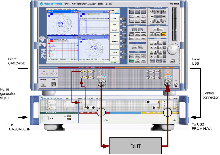
The pulse profile measurement requires the following connections between the network analyzer and the extension unit.
RF connection: Connect SOURCE IN (ZVAX) to SOURCE OUT (NWA) and SOURCE OUT (ZVAX) to SOURCE IN (NWA).
Control connection: Connect USB FROM NWA (ZVAX) to any of the USB type A connectors at the front or rear panel of the NWA.
Pulse generator connection: Connect CASCADE IN (ZVAX) to CASCADE (NWA) using the using the RJ-45 cable supplied with the extension unit.
The DUT is connected between the analyzer ports 1 and 2. The schematic test setup is shown below.
When the extension unit is connected to the network analyzer as described before, it is possible to select the modules to be looped into the signal path(s) and the routing of the pulse generator signals. This is done in the "ZVAX Path Configuration" dialog ("Channel > Mode > ZVAX Path Configuration"). The schematic in this dialog shows all RF modules installed in the extension unit.
The dialog below corresponds to a fully equipped extension unit. The source signal path for port 1 corresponds to the highlighted section in the center.
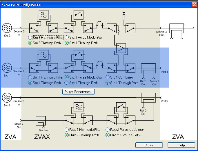
Use the radio buttons in the "ZVAX Path Configuration" dialog to activate the "Src 1 Pulse Modulator". If your extension unit contains a harmonic filter or combiner, select the corresponding through paths.
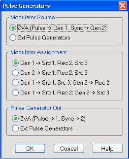
Press "Pulse Generators" and make sure that the "Modulator Source" and the "Modulator Assignment" settings are as shown below.
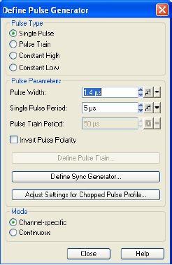
The pulse generator provides single pulses with defined width and period or sequences of pulses (pulse trains). In the example below, a single pulse with a width of 1.4 μs is generated. The pulse is repeated after a pulse period of 5 μs. The second pulse generator signal ("Sync" signal) can be used to synchronize the measurement to the pulse or pulse period.
Click "Channel > Sweep > Sweep Type > Pulse Generator" to activate the pulse generator signal.
Click "Def Pulse Generator..." and configure the "Pulse Parameters" as shown above.
In the "Define Pulse Generator" dialog, click "Define Sync Generator..." and ensure that the "Sync" signal is configured as shown below.
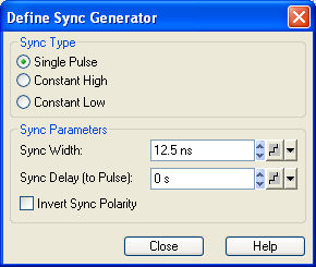
Click "Channel > Sweep > Trigger > Pulse Gen..." to select the pulse generator as trigger source. The dialog "Pulse Gen Trigger" opens. Close it without modifying the default setting ("Rising Edge Sync").
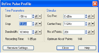
The pulse profile mode of the network analyzer is particularly suited for measurements on pulsed signals. The parameters must be adjusted to the pulse generator settings. In the example below, the start and stop time have been adjusted to view the 1.4 μs pulse width defined previously.
Click "Channel > Sweep > Sweep Type > Pulse Profile" to activate the pulse profile mode.
Click "Define Pulse Profile..." and configure the "Time Parameters" as shown above.
After power calibration and system error correction, the pulsed measurement can be performed as outlined in section Pulse Profile Mode. All measured quantities (S-parameters, wave quantities, ratios etc.) and other trace settings are available.
The following example shows the reflected wave a1, the transmitted wave b2, and the forward transmission coefficient S21 of a DUT with the settings of the previous sections.
The steepness of the edges of the S21 pulse arises from ratioing (b/a) and does not provide a measure for the rise and fall times of the pulse itself.

