With option ZVA-K7, Pulsed Measurements, the analyzer provides pulse profile measurements. The pulsed signal must be generated by external means (e.g. using an R&S ZVAXxx extension unit); see introduction to Pulsed Measurements and Using Pulse Modulators.
 Activating
a basic pulse profile measurement
Activating
a basic pulse profile measurement
Measuring
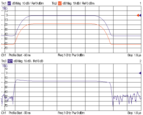
a DUT with a transmission delay.
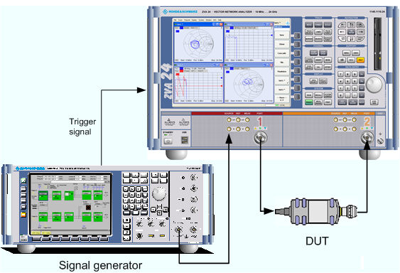
In this example we assume that a pulsed signal (e.g. a signal from an external signal generator) is fed to the SOURCE IN connector of the analyzer port 1 so that it can be used as a port 1 source signal. A DUT is connected between the test ports 1 and 2 of the analyzer; the transmitted pulsed signal is measured at port 2.
We also assume that the signal generator provides a trigger signal which is synchronized to the pulses and applied to the BNC connector EXT TRIGGER on the rear panel of the analyzer. Synchronization of the analyzer and the signal generator by means of a common reference clock is preferable.
The analyzer measures the pulse profile, i.e. the magnitude of the received wave quantity (typically b2) vs. time.
Select the appropriate measured quantity and trace format (Trace – Measure – Wave Quantities – b2 Source Port 1 and Trace – Format – dB Mag).
Click Channel – Sweep – Trigger: External and trigger the measurement on the Rising Edge of the trigger signal.
Click Channel – Sweep – Sweep Type – Pulse Profile.
Click Define Pulse Profile to access the basic measurement settings.
Adjust the Start and Stop times to the pulse width of your signal: Make sure that Stop – Start exceeds the width of a single pulse.
Adjust the Center Freq to the carrier RF frequency of your pulsed signal.
Observe the pulse profile in the diagram area. If desired, vary the If Bandwidth and the Number of Points.
The x-axis of the active diagram is linearly scaled and labeled with the Start and Stop times.
 Switching off the internal
RF generator while an external generator is used can improve the measurement
accuracy. Channel –
Power Bandwidth Average –
RF Off also deactivates external generators, so you have to use
the settings in the Source
section of the Port Configuration dialog
(with option R&S ZVA-K4).
Switching off the internal
RF generator while an external generator is used can improve the measurement
accuracy. Channel –
Power Bandwidth Average –
RF Off also deactivates external generators, so you have to use
the settings in the Source
section of the Port Configuration dialog
(with option R&S ZVA-K4).
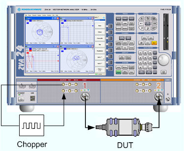
In this example we introduce a chopper between the SOURCE OUT and the SOURCE IN connectors of the analyzer port 1 (see Direct Generator/Receiver Access). The chopper transforms the CW source signal at port 1 into a pulsed signal. In addition a DUT with an attenuation factor of 16 dB and a transmission delay of 100 ns is inserted between port 1 and Port 2 of the analyzer.
The analyzer measures the pulse profile of the reflected and transmitted waves, i.e. the magnitudes of the wave quantities a1 and b2 vs. time and calculates the forward transmission coefficient S21.
Create three traces and select the measured quantities and trace formats (Trace – Measure – Wave Quantities – a1 etc., Source Port 1 and Trace – Format – dB Mag).
Press Channel – Sweep – Trigger: External and trigger the measurement on the Rising Edge of the trigger signal.
Click Channel – Sweep – Sweep Type – Pulse Profile.
Click Define Pulse Profile to access the basic measurement settings.
Adjust the Start and Stop times to the pulse width of your signal: Make sure that Stop – Start exceeds the width of a single pulse.
Adjust the Center Freq to the frequency of your pulsed signal.
Observe the pulse profile in the diagram area. If desired, vary the If Bandwidth and the Number of Points.
Due to the delay and the attenuation introduced by the DUT, the wave b2 is shifted with respect to a1.as shown below.
The magnitude of the S-parameter S21 is distorted at the beginning and at the end of the pulses because the analyzer divides the two wave quantities at equal times.
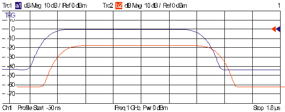
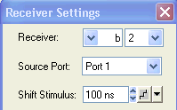
Re-open the Define Pulse Profile dialog and click Receiver Settings...
In the upper part of the Receiver Settings dialog, select the following values:
Close the configuration dialogs and observe the offset-corrected traces.
In the diagram area, the wave quantity is shifted so that the a1 and b2 pulses coincide. This also removes the distortions of the S-parameter.