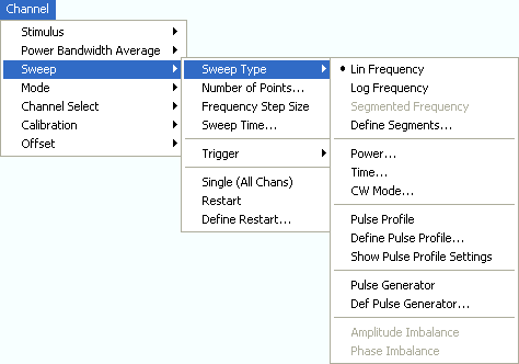
The softkeys in the lower part of the Sweep Type submenu control pulsed measurements (with option ZVA-K7, Pulsed Measurements).
|
|
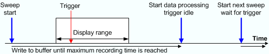
Measurements on pulsed RF signals are required in many areas of RF and microwave technology. Pulsed signals are used in mobile phone applications and radar systems, and amplifiers are typically designed for pulsed rather than continuous wave (CW) conditions. The analyzer performs pulsed measurements in analogy to a time sweep (i.e. at constant receiver frequency), but with a much higher sampling rate of 1/12.5 ns. The raw I/Q amplitudes are written into a ring buffer and processed at the end of each sweep. The buffer size allows for a maximum recording time (sweep time) of 3 ms. Due to the high sampling rate and the large IF bandwidths available, it is possible to obtain profiles for pulse widths from approx. 200 ns to the maximum recording time. Of course it is also possible to measure a sequence of pulses up to the maximum recording time. Pulsed measurements require a trigger signal that is synchronized to the analyzed pulses. The analyzer's trigger system is idle while the data acquired in the last recording period is processed; it is re-armed after data processing is finished. To suppress the noise occurring at high IF bandwidths, sweep averaging is recommended. The RF source signal of the vector network analyzer is continuous, so the pulsed stimulus signals must be generated by external means:
Basic relations: pulse width, repetition interval, IF bandwidth A pulsed RF signal ideally consists of a sequence of periodic rectangular pulses. The pulse width PW and pulse repetition period PRP are shown in the following figure; the ratio PW/PRP is often referred to as the duty cycle.
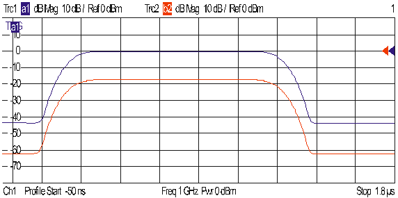
The spectrum of a pulsed signal in the frequency domain has a sin(x)/x envelope, where x is proportional to the duty cycle. The spectral components are equidistant with a spacing of 1/PRP. The analyzer measures and displays the pulses in time domain. To be detected properly, the pulse width must be larger than twice the rise/fall time of the receiver, which roughly corresponds to the inverse of the IF bandwidth. The figure below shows a rectangular pulse with a width of 1 μs, measured in a 10 MHz bandwidth. The rise and fall times are approximately 100 ns.
|
Pulse Profile activates pulsed measurements.
Define Pulse Profile... gives access to the time parameters, the stimulus signal settings, and the receiver settings for pulsed measurements.
Show Pulse Profile Settings opens a screen with an overview of the current settings.
 Activating
a basic pulse profile measurement...
Activating
a basic pulse profile measurement...
Measuring
a DUT with a transmission delay...
Pulse Profile measurements are performed at constant receiver frequency and stimulus power; see background information on pulse profile mode. Pulsed measurements require a trigger signal that is synchronized to the analyzed pulses. Besides all settings are accessible in the Define Pulse Profile dialog.
|
Remote control: |
Opens a dialog to configure the time parameters, the stimulus signal settings, and the receiver settings for pulsed measurements.
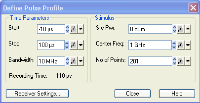
The Time Parameters define the displayed time range and the IF bandwidth:
Start and Stop define the start and stop time in the diagram area relative to the trigger time; they are identical to the Stimulus – Start and Stimulus – Stop parameters. The stop time must be larger than the start time; negative values are allowed.
When the pulse profile measurement is activated (and then every time when the data of the last sweep has been processed) the analyzer immediately starts acquiring data, therefore it is possible to select negative start times (pre-trigger). Moreover, the time of the trigger event does not have to be within the displayed time range (i.e. start and stop time can both be negative or positive).
Bandwidth selects the IF bandwidth for the pulse profile measurements. The measurements are performed with a fixed sampling rate and at fixed frequency, so the bandwidth does not affect the measurement speed. To obtain short rise and fall times of the receiver and measure short pulses, it is preferable to use large bandwidths; see background information on basic relations.
 Filter bandwidths above 10 MHz can be associated
with increased measurement uncertainties. In particular, they tend to
cause overshoot and ringing at the beginning and at the end of the pulses.
Filter bandwidths above 10 MHz can be associated
with increased measurement uncertainties. In particular, they tend to
cause overshoot and ringing at the beginning and at the end of the pulses.
Recording Time indicates the width of the display range, i.e. the difference of Stop – Start time. The calculated recording time is possibly modified if Shift Stimulus or Coupled Section Limit Lines On is active; see Receiver Settings. An error message is displayed if the calculated recording time exceeds the maximum buffer recording time of 3 ms.
 The hardware option R&S ZVA-B7, Pulsed
Measurements, enhances the maximum buffer recording time to 25 ms.
The hardware option R&S ZVA-B7, Pulsed
Measurements, enhances the maximum buffer recording time to 25 ms.
The Stimulus parameters define fixed source and receiver settings for the pulse profile measurement. The parameter settings are also valid for other sweep types.
Source Power is the channel base power; see Power. This setting is relevant if the analyzer is used to generate the pulsed source signal, e.g. with an additional RF switch looped into the SOURCE path.
Center Freq. is the channel base frequency; see CW Frequency. Note that pulse profile measurements are compatible with the frequency-converting mode, so that it is possible to define port-specific corrections to the CW frequency.
No of Points is the number of sweep points displayed; see Number of Points. Due to the fixed sampling period of 12.5 ns and the fixed buffer size, this parameter does not directly affect the measurement speed. Results are interpolated if the number of points differs from the value (Stop – Start)/12.5 ns + 1 (Optimum No of Points).
Receiver Settings opens a dialog with advanced pulse profile settings.
|
Remote control: |
[SENSe<Ch>:]PULSe:TIME... Retrieve raw measured data: CALCulate<Chn> DATA? TSData |
This dialog provides advanced settings for the pulse profile mode. Most of the parameters can be set independently for the different receivers and source ports involved in the measurement.
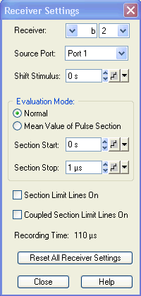
The receiver and source port are selected in the upper part of the dialog.
Receiver selects a receiver for a received wave bi or a reference wave ai (see Receiver).
Source Port contains all analyzer ports and external generators that are available as source ports.
Receiver and source ports scan be selected although they may not be currently used. The analyzer can store predefined receiver settings for arbitrary port configurations.
Shift Stimulus defines an offset time for the current receiver and source port. This is important for measuring DUTs with a noticeable transmission delay.
 Effect of shift stimulus
and examples
Effect of shift stimulus
and examples
Shift Stimulus defines an offset time that is to compensate for a known transmission delay of a DUT. A non-zero shift stimulus value has the following effect:
The trace for the wave quantity assigned to the active receiver is shifted in horizontal direction. A positive value shifts the trace to the left (subtraction of a known delay), a negative value shifts it to the right.
All quantities depending on the shifted wave quantity are calculated with the corrected time reference. In the example below, the S-parameter S21 is calculated as S21(t) = b2(t + <Shift stimulus>)/a1(t).
The displayed Recording Time is extended to cover the delayed wave.
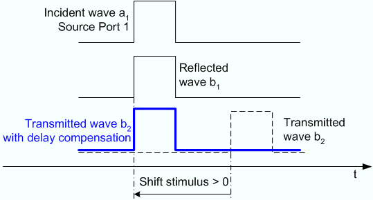
The example above illustrates the importance of a correct delay compensation for the calculation of S-parameters, ratios and other derived quantities in the time domain. Without compensation, the two pulses for a1 and b2 do not overlap so that no meaningful S-parameter calculation is possible.
Example: S-parameter measurement for a DUT with known delay Dfw and Drev in forward and reverse direction. The DUT is connected between port 1 and port 2 of the analyzer. The test setup is fully calibrated so that the reference planes are at the DUT's input and output ports.
|
Receiver: a1 |
Receiver: b1 |
Receiver: b2 |
|
Receiver: a2 |
Receiver: b1 |
Receiver: b2 |
The Evaluation Mode specifies how the wave quantity assigned to the current receiver and source port is displayed. In Normal mode, it is displayed as measured (pulse shape). If Mean Value of Pulse Section is selected, the wave quantity is replaced by its mean value (magnitude and phase) averaged over a configurable time interval [Section Start, Section Stop].
Effect of averaging, definition
of the time interval
Mean Value of Pulse Section has the following effect:
The trace for the wave quantity assigned to the active receiver is replaced by a constant trace.
All quantities depending on the wave quantity are based on the averaged values.
The displayed Recording Time is extended to cover the specified pulse section.

Section
Start and Section Stop
can be negative and even outside the displayed time range, however, Section Start must be smaller than
Section Stop. A stimulus shift
also shifts the Section Start
and Section Stop values.
The remaining settings in the dialog are general; they do not depend on the selected receiver and source port.
Section Limit Lines On places two vertical lines into the diagram(s), indicating the selected Section Start and Section Stop. The section limits can be modified using drag-and-drop.
Coupled Section Limit Lines On couples the section limits (and the section limit lines) for all receivers and source ports and in all channels. The evaluation mode and the Shift Stimulus values are still independent. As a typical application, it is possible to create two channels, display the same wave quantity with different evaluation modes (pulse shape and average), vary the section limits in normal evaluation mode (pulse shape) and monitor the effect on the average trace.
Recording Time indicates the width of the display range, possibly modified if Shift Stimulus or Coupled Section Limit Lines On is active; see background information above. An error message is displayed if the calculated recording time exceeds the maximum buffer recording time of 3 ms.
Reset All Receiver Settings the parameters in the dialog for all receivers and source ports.
Measuring
a DUT with a transmission delay...
|
Remote control: |
[SENSe<Ch>:]PULSe:COUPled[:STATe] |
Gives an overview of the current time and stimulus settings for pulsed measurements. The info screen also display softkeys to Print the contents, save them to a file (Print to File) or Close the screen.

|
Remote control: |
Settings can be retrieved using the query form of the commands. |