|
|
|
|
|
|
|
|

| Notice Information in this document is provided in connection with Intel products. No license, express or implied, by estoppel or otherwise, to any intellectual property rights is granted by this document or by the sale of Intel products. Except as provided in Intel’s Terms and Conditions of Sale for such products, Intel assumes no liability whatsoever, and Intel disclaims any express or implied warranty, relating to sale and/or use of Intel products including liability or warranties relating to fitness for a particular purpose, merchantability, or infringement of any patent, copyright or other intellectual property right. Intel products are not intended for use in medical, life saving, or life sustaining applications. Intel retains the right to make changes to specifications and product descriptions at any time, without notice.
Copyright(c) Intel Corporation 1996. Third-party brands and names are the property of their respective owners. |
CONTENTS: |
Intel's MMX™ Technology processes multiple integer data items in parallel, 64 bits at a time. It can speed processing of pixels in 3D graphics, compared to straight Intel Architecture code which handles at most 32 bits at a time. Thus MMX technology may enable higher frame rates and/or higher quality images.
MMX technology best fits 16-bit or 24-bit color rendering, although it can assist 8-bit also. Intel and other developers have written 3D rendering code using MMX technology. Benefits were found in alpha blending, Gouraud shading, Z-Buffering, pixel-depth conversion, image copying, bilinear filtering, texture mapping, and procedural texturing. MMX technology algorithms can be 2x to 4x faster in 16 and 24-bit color; but 8-bit color algorithms typically speedup only 30% or less. These speedups come from:
For best performance, SW designers using MMX technology must carefully tune for system bandwidths. Existing PCI bus and graphics chips constrain throughput to graphics cards to about 80 MBytes/sec for writes, and far less for reads. Likewise current main-memory systems typically have less than 160 MBytes/sec total sustainable bandwidth.
However, the external cache of the CPU has more than twice this speed, and the internal cache more than 10x the main memory speed. Code designers should ensure their algorithms and data stay in the caches as much as possible, and should avoid reading data from the graphics card (via the PCI bus). Even the new A.G.P. bus is significantly faster for writes than for reads from the CPU, so software should avoid reading directly from the RAM on the graphics card. The A.G.P. bus facilitates sharing of main memory regions at high bandwidth by both the graphics chip and the CPU.
Creating 3D applications and content for MMX technology is very much like creating for 3D hardware accelerators, as both use 16-bit or 24-bit RGB formats. In some cases, software rendering runs faster, and certainly more flexibly, than current 3D hardware. In other cases, it makes sense to combine foreground objects and special effects, rendered in software, with hardware-rendered backgrounds. Hardware imposes certain overhead in setting-up registers and synchronization, but of course has higher bandwidth to graphics memory because both memory and the accelerator are on the same end of the PCI (or other) bus.
This paper was written for programmers and technology managers, as an overview of MMX technology for 3D graphics. It provides hints on the most beneficial tactics and the tradeoffs in implementations.
Rather than writing custom code, programmers may want to use an available 3D API library built on MMX technology, such as Microsoft's Direct3D*, Criterion's Renderware*, or Argonaut's BRender*. But this paper gives insight to rasterization in custom code. We assume the reader is familiar with 3D graphics terms and concepts.
| Figure 1: 3D Rendering Pipeline. |
|---|
|
Each vertex consists of
Other features of vertices are typically maintained as a
"state" variable of the rendering pipeline. These variables
must be changed explicitly each time a new texture, shading, blending,
or lighting model is desired. Typical state variables include:
For more thorough discussion of vertex information and states in a
"typical" 3D library, refer to
Microsoft's Direct3D* descriptions. In fact, the Direct3D
rendering pipeline incorporates MMX technology in many of the
steps discussed below, and readers are encouraged to experiment with
Direct3D.
The sequence of operations on vertices can vary, but it
usually follows a pattern like:
Perfect perspective
correction requires two divides PER PIXEL, or a divide and two muliplications.
Perspective correction can be approximated without divides,
by adding second-order (quadratic) differentials to the du & dv
values at each pixel. These differentials are labeled ddu & ddv.
See the
app note on perspective-correction quadratic approximation. Alternatively,
the algorithm can do the divide once per 8 or 16 pixels,
and linearly interpolate for the intervening 7 or 15 pixels.
While the above setup operations can benefit from the parallelism
of MMX technology, the number of calculations is limited, and they
often use floating point arithmetic.
Much more benefit accrues in the subsequent steps of drawing each
pixel on each scanline.
To draw each pixel, a variety of operations occur, depending
on the state variables of the renderer discussed earlier. The order of
operations may vary, and may not include all of the following, but
generally they are:
MMX instructions can also generate a
without requiring a bitmap source for texture.
Thus less memory bandwidth and space are consumed, and less aliasing
or blockiness occurs for magnified views.
MMX Technology does best on 16-bit hicolor and 24-bit true color
data. The packed add, multiply, and logical operations actually
make 24-bit the only format attractive for calculations, as
three 8-bit R, G, and B components or 8.8 bit fixed point
(48 bits total for RGB).
After completing calculations (like Gouraud shading, alpha,
etc...), the algorithm can convert to RGB16 (555 or 565) for updating
the display buffer. MMX technology has no built-in arithmetic
nor packing for 5-bit chunks.
24-bit internal operations allow high-quality features which are not
possible with 8-bit palettized color, including:
Of course, the amount of graphics memory in the system determines
whether the application can use 16-bit or 24-bit color. For 1MB
graphics cards, the app probably may stay with 8-bit palettized
(640 x 480 x 2bytes requires 600KB, which can fit in 1MB only if
not double-buffered, or if the backbuffer is in system memory).
For 2MB or 4MB, 16-bit is attractive, as the 1.2MB requirement
of 640 x 480 double-buffered still leaves 800KB for texture caching
and/or Z-buffering.
Eight-bit color does permit moving 8 pixels simultaneously with
a single MOVQ instruction. It also permits 16 simultaneous
compares and/or merges, given the
dual-pipeline MMX technology execution units
and instruction "pairing".
Unfortunately, 8-bit palettized rendering requires reading one byte
at a time from a texture palette.
Traditionally, 8-bit rendering code for older processors
played "speed tricks" which actually degrade performance
on newer CPUs. These should be avoided, for high speed on the
Pentium(R) processor and Dynamic Execution(TM) processors.
Examples include:
3D rasterization is data-bandwidth intensive, and performance
problems often occur due
to inability to move data between main memory, CPU caches,
CPU registers, graphics memory, and buses. As shown in Figure 4,
peak bandwidths vary widely in the various pieces of the system.
Most PC systems have two caches, one on the CPU chip called "L1" (Level One)
and a larger external cache called "L2" (Level Two).
Software optimized to utilize the caches can have 2x to
10x higher performance, as the caches run 2x to 10x as fast
as main memory.
Application SW cannot explicitly control the caches. It cannot
command them to hold a specific data item, as the hardware attempts
to keep the most useful data cache-resident.
For best performance, all accesses should be to cached data,
in the order that the HW brings it into the cache.
Accesses should be on the natural boundaries of the cache HW (quadwords
and 32-byte cache lines). Apps should try to re-use data as much as
possible once it is present in the cache. Unfortunately, SW cannot
explicitly test whether particular data items are cached, and
testing would cut the performance anyway. SW sequences can
be cleverly crafted to get data efficiently into and out of the caches.
SW can utilize the caches efficiently by:
Even for non-cached memory locations, such as graphics card
RAM or uncacheable main-memory regions, SW optimization
of accesses can offer speedup:
Figure 5 shows the huge variations in memory and graphics
bandwidth, depending on how carefully the data are arranged
and accessed. The measurements are sustained rates for
very small code loops, on a Pentium(R) processor 166MHz system
with:
The theoretical peak bandwidth for reads from the
L1 cache would be 166 MHz * 8 bytes, or 1328 MB/s. Actual
measurements were only 2/3 as large, due to the loop overhead.
Also note that the uncached main memory copy numbers (at ~97 MB/s
for QWORDS) were lower than expected, since they result from
continual interleaving of
reads and writes to different DRAM pages. To improve this bandwidth,
if the source data can be cached, the algorithm may read several L1
cache lines of source from one DRAM
page by touching every 32nd byte, then copying them all out of
cache with sequential continuous writes. Of course, your mileage may vary.
How should these maximum-bandwidth measurements be used ? Well, they
tell how many CPU clocks are available for computation for each write
or read. For example, writing to main memory at ~175 MBytes/sec means
about one 8-byte write every 7 CPU internal clocks at 166 MHz. Thus
SW can do between 7 and 15 computation instructions per write,
depending on the amount of pairing. But if the computations require
two inputs for every output, as in the case of alpha blending, then
another 350 MBytes/sec would have to been read concurrently. If these
inputs come from the L1 cache, theoretically the 175 MB/s output
remains feasible. More likely, however, is reading from main memory
at least one input per computation, so that the net output will drop
to less than half the max measured 175 MB/s. Optimization involves
balancing the computation with memory accesses, beyond just arranging
the data most efficiently.
Performance benefits from MMX technology in 3D rendering
vary widely. Naive implementations may yield no speedup at
all.
Intel's VTune
performance-tuning tool can help significantly in analyzing
MMX technology code. Generally, speedup requires:
Experience has shown that the MOVQ instruction and the
"extra" registers alone
can yield a 30% pixel-rate speedup in 3D rendering in real applications,
whether 8-bit, 16-bit, or 24-bit coloring. For Gouraud shading
at 24-bit color, MMX technology proved 2x faster than straight
Intel architecture instructions. For bilinear-filtered texture
mapping at 16-bit, it was more than 3x faster. For Z-buffering,
overall rendering sped up from 10% to 60%, depending on the
object size and the algorithm.
On two rendering libraries, we have measured on MMX technology Pentium processor
166MHz systems, complete SW pipeline pixel rates of 1 Mpix/s to 20 Mpix/s
for RGB16. The higher number came from low-polygon count, non-Z-buffered,
non-alpha, with a mix of flat, Gouraud, and point-sampled textured objects.
The lower number came from turning on all those features and
texture filtering. The numbers
will improve as CPU clock rates grow, P6-family processors proliferate,
and the rendering algorithms mature.
Creating 3D applications and content for MMX technology
is very much like creating for 3D hardware accelerators,
as both use 16-bit or 24-bit RGB formats.
In some cases, software rendering runs faster, and
certainly more flexibly, than current 3D hardware.
In other cases, it makes sense to combine
foreground objects and special effects, rendered in software,
with hardware-rendered backgrounds. Hardware imposes certain
overhead in setting-up registers and synchronization,
but of course has higher bandwidth to graphics memory.
So MMX technology does not make 3D hardware unnecessary, nor
does HW make MMX technology unnecessary.
SW 3D rasterization can accomplish some things that
hardware cannot. Procedural and animated textures are one
example, which create a texture mathematically in real-time.
This reduces the artifacts which come from texture magnification,
minification, and filtering, versus a standard bitmap-based
mapper. Procedural textures can add dynamic realism, such as the
appearance of wave-motion in water.
For small triangles (less than 50 pixels), the SW setup overhead
for hardware accelerators may exceed the speed gain of
hardware rasterization. For example, the controlling program may
need to send 30-40 bytes per scanline to a low-end 3D accelerator, for
each polygon. If that scanline is less than 20 pixels long, a SW-only
renderer could have calculated and displayed the pixels themselves
in less time. Likewise, a high-end triangle-capable 3D accelerator
still needs 40-100 bytes setup per triangle, which may exceed the bytes
in the rendered pixels.
Typical triangle sizes in typical scenes follow a bipolar distribution,
with many small (50 pixel or less) triangles, and a few large
(500-100,000 pixel) triangles. Figure 6 shows a flight simulator
scene distribution: airplanes, buildings, and trees are made
up of small polygons, while the ground, clouds, and sky are large polygons.
In this application, SW could draw those small polys,
and concurrently hardware could draw the large.
Of course, the merging of SW and HW rendered polys or objects
can prove complex. If they are to abut one another (E.G., SW draws
a snowcap on a HW mountain), then both rasterizers must be following
the same rules about subpixel locations and edge-inclusion. Furthermore,
if interpenetrating objects may exist, or if SW does not pre-sort objects
to ensure hidden surface removal, then a Z-buffering merge operation
will be required. Finally, some locking and synchronization mechanism
must be employed to prevent accelerator HW and SW (the CPU) from
writing to the same pixels at the same time, and to prevent one from
writing the next frame's pixels ontop of the other's current-frame pixels.
Adapting 3D rendering software to MMX technology can yield
significant performance and quality improvements, for 16-bit
and 24-bit color. To a lesser extent, even 8-bit color
applications derive some speed increase.
The adaptation requires rewriting the inner loops of the
3D rasterization pipeline. Experience has shown the effort
to be 4-8 person-weeks, for a typical PC game application.
Some optimization
of data structures may also be required -- for example, aligning
arrays on 8-byte boundaries, grouping together data types
in individual arrays rather than in heterogenous structures, and
using 16-bit color in textures. Also, it requires tuning data
access and algorithms to optimize cache utilization.
In some cases, a mix of hardware-accelerated rendering and
a software pipeline can produce better results than either alone.
MMX technology software rendering can implement new and/or
flexible algorithms, such as procedural texturing, specular
highlights, and dynamic lighting.
Developers often use floating-point data and calculations for
3D Geometry, instead of integer or MMX technology.
Geometry calculations
include matrix & vector multiplies and additions. Reasons for
floating point usage include: broader dynamic range, more precision,
and simplicity.
If integer or fixed point values are used, the
programmer must constrain the data to reside in a limited range,
such as +/-32k for 16-bit numbers. And overflow/underflow checking
must be done on products and sums.
However, for applications already written with 16-bit integer or
16-bit fixed-point geometry, MMX technology offers speedup in matrix
and vector manipulations. See the app notes listed below for details:
Rasterization
Figure 2 shows a typical 3D rasterization dataflow. For input, it
receives transformed, lit vertices, and linking structures such as
discrete triangles (three vertices each) or triangle meshes. In a mesh, each
new vertex defines a new triangle, whose other two vertices are the
preceeding two in the mesh list.
For final output, the pipeline draws images on a CRT screen. The
circled "M" symbols show areas where MMX technology can add quality or performance.
Figure 2: 3D Rasterization. Note: the sequence of operations may vary.
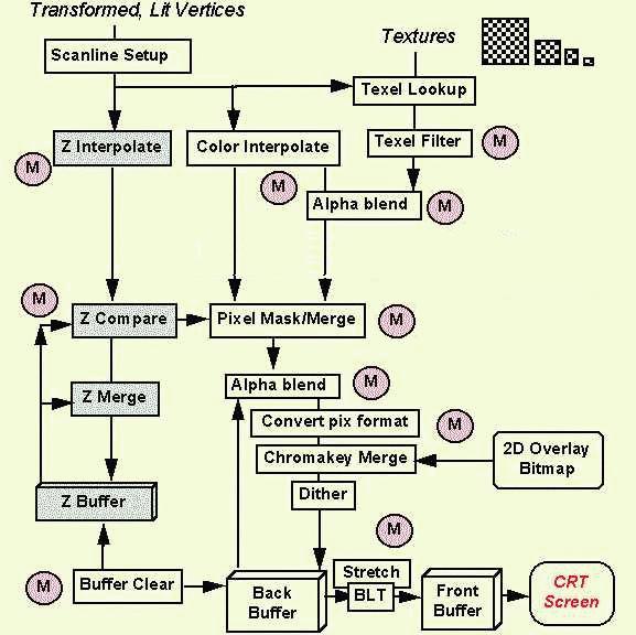
Figure 3: Perspective Correction Example. The striped cube on the left
lacks correction, and shows discontinuties in textures at triangle edges.
Pixel Depth Tradeoff: 8 bit, 16 bit, 24 bit
System Bandwidth Considerations
Figure 4: Peak Hardware Bandwidths for Two Typical Systems
For more information on the CPU caches, refer to the
MMX Technology Developer's Manual, chapter 3.
Other Memory Optimizations
Systems using P6-family processors are even more sensitive to caching,
alignment, and sequentiality (burst-ability) of writes.
Figure 5: Measured Memory and Graphics Bandwidth for Pentium(R)
Processor 166MHz
82430HX systems
for various types of access
Overall Performance Predictions
Software and Hardware Acceleration
Figure 6: Polygon Size Distribution for a Sample 3D Flight Simulator Scene
Conclusion
Appendix: Myths and Realities
Myths Realities CPU is
bandwidth-bottlenecked
by memory & PCI 166 MHz CPU & PCI do 640x480,30fps,16bpp
(20 MPix/sec) MMX technology is
no use for
colorindex (8-bit) MMX technology can add 10%-30% for 8-bit color
Using FP (Floating Point) mixed with
MMX technology is too slow (transition penalty) In most cases, the penalty can
be worked-around to rarely occur, by modularization of FP code. MMX technology is
slow for
16bit RGB565 or 555 Converting from RGB888 to 565 or 555 takes about three
clks/pixel. 3D HW will make SW
rendering
unneeded HW & SW are complementary. They can
enhance or augment each other. SW is great at
smaller objects & special effects. MMX technology
code
development takes a long time. Most apps require MMX
instructions only in inner loops, and the effort is typically 4-8
person-weeks.
Appendix: MMX Technology for Geometry ?
Appendix: Glossary of 3D Terms, and Useful Links
* Legal Information © 1998 Intel Corporation