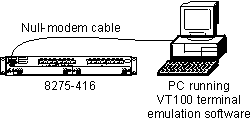
Figure 9. Out-of-band connectivity - locally attached terminal
 (artname: fgb0a023.EPS) |

This chapter explains the types of connections that you can use to physically access the switch. Once the connection is established, you will configure the IP information (either through the terminal interface or through DHCP or BootP), and then choose which user interface you want to use to manage it. Therefore, all interfaces support configuring the switch and obtaining information from it, thus providing greater flexibility in how you manage your switch.
There are two connection methods used to physically access the switch:
Table 10 outlines the user interfaces that are available depending on your method of connection.
Table 10. Connection methods and available user interfaces
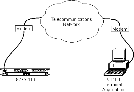
Out-of-band connection lets you access your switch through the serial EIA 232 port. It can be either through a locally attached PC running VT100 terminal emulation software, or through a remotely attached PC running VT100 terminal emulation software connected to a modem.
To establish out-of-band connectivity using a locally attached terminal, make the physical connections and set up using the following procedure:
Figure 9. Out-of-band connectivity - locally attached terminal
 (artname: fgb0a023.EPS) |
To establish out-of-band connectivity using a remotely attached terminal, make the physical connections using the following procedure:
Figure 10. Out-of-band connectivity - remotely attached terminal
 (artname: fgb0a022.EPS) |
To configure the IP information, see Configuring your switch for details.
| Note: | To use in-band connectivity, you must configure the switch with its IP information (IP address, subnet mask, and default gateway), and have a path available through the Default VLAN (VLAN 1). See Configuring your switch for configuring BootP or DHCP and IP information for your switch. |
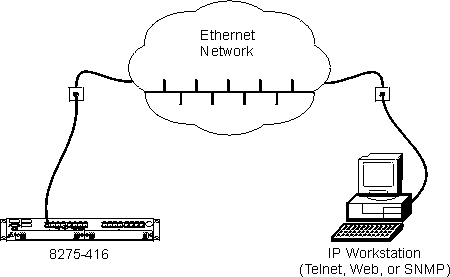
In-band connectivity allows access to the switch using the data network (as shown in Figure 11).
 (artname: fgb0a017.EPS) |
Telnet console management can be performed through an Ethernet port (in-band connection). You must configure an IP address before using Telnet console management (Refer to Configuring your switch for initially configuring IP information for your switch.
You can use any Telnet application that emulates a VT100 terminal to establish a Telnet console management session. Up to five concurrent Telnet sessions are supported. For security, the Telnet session can be automatically logged off after a certain time of inactivity. You can configure the time of inactivity from 0 to 160 minutes; the default is 5 minutes.
The terminal interface is menu-driven and can be used to manage the switch through the EIA 232 port or a Telnet session. For security, a login user ID and password are required. Multiple user IDs and associated passwords can be created. Two levels of access privileges are supported: read/write and read only.
See Appendix D, Interface Conventions for the Console for a description of the terminal keys. You may need to configure your terminal application to enable use of these keys.
See Using the Terminal Interface for a description of the terminal interface panels.
The switch has an SNMP agent that supports SNMP Version 1 which allows it to be managed by any SNMP-based application (for example, Nways Campus Manager which supports the MIBs that the switch supports). See Using the SNMP Interface for details about the MIBs supported by the switch.
The switch has a Web server that supports HTTP 1.1 or later, and HTML 4.0 or later. Your Web browser must support HTTP 1.1 or later, HTML 4.0 or later, and JavaScript(C) 1.2.
You can use the Web interface to access and change switch parameters. Menus similar to those available through the terminal interface are also displayed by the Web browser. To access the switch from a Web browser, you must have configured the IP information for the switch. You will need a valid login user ID and password. The accepted user IDs and passwords are the same as those configured for the terminal interface.
The is no specific logout command to end a Web session. The Web session will be automatically logged off after a period of inactivity. The inactivity timeout value that is configured for the Telnet session is used by the Web interface.
See Using the Web Interface for starting and using the Web interface.