The commands in the Lines submenu define limits for the measurement results, visualize them in the diagrams and activate/deactivate the limit check. The analyzer provides upper, lower, and ripple limits. Besides the menu provides a horizontal line for each trace.
A limit line is a set of data to specify the allowed range for some or all points of a trace. Typically, limit lines are used to check whether a DUT conforms to the rated specifications (conformance testing).
The upper limit line defines the maximum value for the trace points.
The lower limit line defines the minimum value for the trace points.
The ripple limit defines the maximum difference between the largest and the smallest response value of the trace.
A limit check consists of comparing the measurement results to the limit lines and display a pass/fail indication. An acoustic warning and a TTL signal at the USER CONTROL port can be generated in addition if a limit is exceeded.
Upper and lower limit lines are both defined as a combination of segments with a linear dependence between the measured quantity and the sweep variable (stimulus variable). Similar to this segmentation, ripple limits may be defined in several ranges. The limit lines can be stored to a file and recalled. Data or memory traces can be used to define the segments of an upper or lower limit line. Moreover it is possible to modify the upper and lower limit lines globally by adding an offset to the stimulus or response values.
|
|
|
Define Limit Line opens a dialog to define, save or recall limit lines.
Show Limit Line displays or hides the limit line associated to the active trace.
Limit Check activates or deactivates the limit check.
The commands in the second section of the submenu configure the ripple check.
Global Beep activates or deactivates the acoustic signal indicating a limit or ripple limit excess.
Global Check activates a global (composite) limit and ripple limit check on all traces in the active setup.
TTL Out Pass 1/2 activates or deactivates a TTL output signal at the USER CONTROL connector indicating whether the trace was passed or failed.
Horizontal Line... displays or hides the horizontal line of the active trace and changes its position.
Limit lines are available for all Cartesian diagram types (Trace – Format). For polar diagrams, the functions of the Lines submenu except the Global Check are grayed. The limit lines are hidden and the limit check (except the global check and the global ripple check) is disabled when a Cartesian trace format is replaced by a polar diagram.
Opens a dialog to define the limit line for the active trace on a segment-by-segment basis. In each segment the limit line is defined as a straight line connecting two points.
 Creating
limit lines with minimum effort
Creating
limit lines with minimum effort
Choose one of the following methods to efficiently create and handle limit lines:
To define a limit line with only a few segments, use Add Segment and edit each segment in the segment table individually.
Use the multiselection feature to edit several limit line segments at the same time.
Select a data or memory trace as a limit line (Import Trace) or import a trace stored in a file (Import File).
Save your limit lines to a file so you can re-use or modify them later sessions (Save Limit Line, Recall Limit Line).
The Define Limit Line dialog contains a table to edit the individual segments of the limit line; see below. The active trace is indicated in the title bar of the dialog. The three buttons below the table extend or shorten the segment list.
The buttons to the right of the table are used to import and export limit line data.
opens a box to select a trace that can be used to define a limit line.
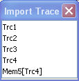
The box contains all data or memory traces of the active channel. As soon as a trace is selected, the Properties of Imported Segmentsdialog with further global import options is opened.
Calls up a standard Import File dialog to load a limit line from a trace file. The limit line import is analogous to the import of traces. Trace files are ASCII files with selectable file format. After the trace file is selected, the Properties of Imported Segmentsdialog with further global import options is opened.
Imported traces are polygonal curves with n points and n – 1 segments. The number of points n is set via Channel – Sweep – Number of Points. The n – 1 segments are appended to the current segment table for further editing. Existing limit line segments are not overwritten.
To import a limit line file (*.limit) you can also use
the Windows Explorer and simply double-click the file or drag and drop
the file into the NWA application. You have to switch on the limit check
separately. Use the paste
marker list
for convenient entry of Start
and Stop
values.
 Columns
in the segment table
Columns
in the segment table
The table contains an automatically assigned current number for each segment plus the following editable columns:
Type indicates whether the segment belongs to an Upper or a Lower limit line, or if the limit check at the segment is switched Off. Switching off the limit check does not delete the segment but changes its screen color.
Start Stimulus is the stimulus (x-axis) value of the first point of the segment.
Stop Stimulus is the stimulus (x-axis) value of the last point of the segment.
Start Response is the response (y-axis) value of the first point of the segment.
Stop Response is the response (y-axis) value of the last point of the segment.
The limit line segment is calculated as a straight line connecting the two points (<Start Stimulus>, <Start Response>) and (<Stop Stimulus>, <Stop Response>); see Rules for Limit Line Definition.
In the Define Limit Line dialog it is possible to edit several limit line segments at the same time. Selection of one or more segments (use the left mouse key and the Shift key of an external keyboard) and a right-click on the dark grey Seg. area opens a context menu:
The context menu provides the following functions:
Modification of all entries in the segment table: Type, start and stop values for the stimulus and response variable.
Definition of an offset for response and stimulus values in analogy to the Properties of Imported Segments dialog.
Delete the selected segments.
Merge the selected segments to a single new segment.
|
Remote control: |
The analyzer places very few restrictions on the definition of limit line segments. The following rules ensure a maximum of flexibility:
Segments do not have to be sorted in ascending or descending order (e.g. the Start Stimulus value of segment no. n doesn't have to be smaller than the Start Stimulus value of segment no. n+1).
Overlapping segments are allowed. The limit check in the overlapping area is related to the tighter limit (the pass test involves a logical AND operation).
Gaps between segments are allowed and equivalent to switching off an intermediate limit line segment.
Limit lines can be partially or entirely outside the sweep range, however, the limits are only checked at the measurement points.
The following figure shows a limit line consisting of 3 upper and 2 lower limit line segments. To pass the limit check, the trace must be confined to the shaded area.
As a consequence of the limit line rules, the limit check will always pass a DUT if no limit lines are defined.
The Properties of Imported Segments dialog appears before a trace is imported into the Define Limit Line dialog.
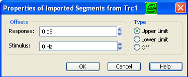
The dialog assigns common properties to all limit line segments generated by the imported trace.
The analyzer uses a simple ASCII format to export limit line data. By default, the limit line file has the extension *.limit and is stored in the directory shown in the Export Limit Line and Import Limit Line dialogs. The file starts with a preamble containing the channel and trace name and the header of the segment list. The following lines contain the entries of all editable columns of the list.
The limit line:
is described by the limit line file:
|
Remote control: |
MMEMory:LOAD:LIMit
"Trc_name","file_name"
|
Shows or hides the limit line associated with the active trace in a Cartesian diagram area. A checkmark appears next to the menu item when the limit line is shown.
In the diagram, upper and lower limit lines can be displayed with different colors. Limit line segments with disabled limit check (see Define Limit Line) can also be colored differently. The limit line colors are defined in the Define User Color Scheme dialog (Display – Display Config. – Color Scheme...).
 Display of the limit line and limit check are independent
of each other: Hiding the limit line does not switch off the limit check.
Display of the limit line and limit check are independent
of each other: Hiding the limit line does not switch off the limit check.
|
Remote control: |
Switches the limit check of the active trace on or off. A checkmark appears next to the menu item when the limit check is enabled.
When the limit check is switched on, a PASS or FAIL message is displayed in the center of the diagram. If the limit check fails at a measurement point, the two trace segments to the left and right of the point can change their color. The Limit Fail Trace color is defined in the Define User Color Scheme dialog (Display – Display Config. – Color Scheme...). An acoustic signal (Global Beep) and a TTL signal indicating pass or fail can be generated in addition.
Limit check and display of the limit lines
are independent of each other: With disabled limit check, the limit line
can still be displayed.
If no limit lines are defined for the active trace, the limit check can
be switched on but will always PASS
the trace.
Limits are checked at the actual measurement points, whereas a limit failure is indicated for the trace segments on both sides of a failed point. A small number of points causes wide trace segments so that the out-of tolerance regions can appear wider as they are.
Markers show interpolated values. As a consequence, a trace segment can be failed, whereas a marker placed on the segment may show a response value within the allowed range. This is shown in the example below, with an upper limit line at 26 dB, and a marker response value of 25.968 dB. The small circles correspond to the sweep points; the orange part of the trace is failed.
|
Remote control: |
CALCulate<Chn>:LIMit:STATe
ON | OFF |