The Measure submenu selects the quantity to be measured and displayed.
|
|
|
S11, S12, S21, S22 select the four elements of the standard 2-port scattering matrix (S-parameters).
More S-Parameters opens a dialog to select S-parameters for multiport measurements or mixed mode S-parameters.
Ratios opens a submenu to select and define ratios of wave quantities.
Wave Quantities opens a submenu to select the absolute (unratioed) power of the analyzed signals (wave quantities).
Impedance opens a submenu to convert reflection S-parameters into matched-circuit impedances (converted Z-parameters).
Admittance opens a submenu to convert reflection S-parameters into matched-circuit admittances (converted Y-parameters).
Z-Parameters opens a dialog to select arbitrary open-circuit impedance parameters describing a linear circuit.
Y-Parameters opens a dialog to select arbitrary short-circuit admittance parameters describing a linear circuit.
Stability Factor selects one of the three factors K, μ1 or μ2 to assess the stability of linear circuits (e.g. amplifiers).
Imbalance opens a dialog to select the imbalance for balanced ports.
All S-Params displays all S-parameters that the analyzer can measure in the appropriate diagram areas.
DC Inputs selects and configures the measurement of DC powers and the Power Added Efficiency (PAE).
Power Sensor opens a configuration dialog for the measurement of wave quantities using an external power meter.
Noise Figure selects the results of the Noise Figure measurement (with option R&S ZVAB-K30).
 Port
assignments of the DUT and the analyzer
Port
assignments of the DUT and the analyzer
S-parameters S<out>< in> characterize the Device Under Test, so the indices <out> and < in> denote the output and input ports of the DUT. Analogously the waves a1 and a2 are referred to as incident waves, b1 and b2 to as outgoing waves.
The analyzer measures the waves a1, b1, ... at its own test ports in order to obtain S-parameters, ratios and other derived quantities. The test ports of the analyzer are numbered, so it is convenient to use them as a reference, defining port number n of the DUT as the port connected to test port n of the analyzer. With this convention the waves an and bn have the following meaning:
an is the wave transmitted at test port no. n of the analyzer (stimulus signal) and fed to port number n of the DUT (incident wave).
bn is the wave transmitted at port number n of the DUT (response signal) and received at test port no. n of the analyzer (received wave).
 The analyzer offers various diagrams and display formats
to visualize the results. The analyzer places no restriction on the formats
that are available for each measured quantity. However, to keep the interpretation
simple, it is recommended to select an appropriate display format; see
Trace
- Format.
The analyzer offers various diagrams and display formats
to visualize the results. The analyzer places no restriction on the formats
that are available for each measured quantity. However, to keep the interpretation
simple, it is recommended to select an appropriate display format; see
Trace
- Format.
Select one of the four elements of the standard 2-port scattering matrix (S-parameters).
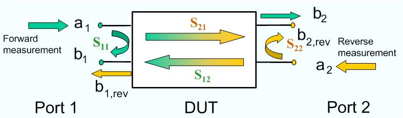
The S-parameters are the basic measured quantities of a network analyzer. They describe how the DUT modifies a signal that is transmitted or reflected in forward or reverse direction. S-parameters are expressed as S<out>< in>, where <out> and <in> denote the output and input port numbers of the DUT.
A full 2-port S-parameter measurement involves 2 stages (referred to as partial measurements) with interchanged drive and receive ports. The analyzer automatically switches the internal power sources and the receivers to obtain the desired S-parameters.
|
Remote control: |
CALCulate<Ch>:PARameter:MEASure
"<Trace_Name>", "S11" | "S12" | "S21" |
"S22"
Create
new trace and select name and measurement parameter:
|
Opens a dialog to select S-parameters for multiport measurements (including the 2-port S-parameters) or mixed mode S-parameters.
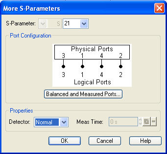
The More S-Parameters dialog provides the following settings:
S-Parameter selects the type (left pull-down list) and the port number assignment (right pull-down list) of the S-parameter. Mixed mode parameters are only available if a balanced port configuration is active. They are expressed as S<mout><min>, where <mout> and <min> denote the output and input port modes. The port numbers are assigned in the order S<out>< in>, where <out> and <in> denote the output (response) and input (stimulus) port numbers of the DUT.
The graphics in the Port Configuration panel depicts the current port configuration. Balanced and Measured Ports opens the Balanced Port and Port Groups dialog to define the properties of the test ports. Single-ended (unbalanced) S-parameters are assigned to the physical test ports of the analyzer. Balanced S-parameters are assigned to logical test ports. Selecting a balanced port configuration with logical test ports means that the unbalance-balance conversion is switched on and that the analyzer provides mixed mode S-parameters.
Detector selects the algorithm that is used to calculate the displayed trace from the individual measurement points. In the average (AVG) detector mode, it is possible to define the detector observation time (Meas. Time) for each single measurement point. The average detector is particularly suitable for S-parameter measurements in parallel to a noise figure measurement (option R&S ZVAB-K30), where an alternative reduction of the measurement bandwidth is not possible. For an overview of detector settings refer to section Detector.
The
port configuration is valid for all traces in the channel
The settings made in the Balanced and Measured Ports dialog are channel settings and therefore apply to all traces assigned to the channel (Balanced and Measured Ports is also accessible through Channel –Mode–Port Config...). Within a channel the analyzer measures either single-ended or mixed mode parameters. If a balanced test port configuration is selected the single-ended parameters assigned to the channel are converted into mixed mode parameters.
Single-ended
and mixed mode S-parameters
|
Remote control: |
CALCulate<Ch>:PARameter:MEASure
"<Trace_Name>", "S11" | "S12" | "S21"
| "S22"
Create
new trace and select name and measurement parameter:
|
The analyzer measures single-ended (unbalanced) parameters (S-parameters, impedances, admittances, Z-parameters, Y-parameters) unless a balanced port configuration is selected. In the More S-Parameters dialog and the analogous dialogs for the other quantities, the left parameter selection field shows the parameter type (S, Y, Z) and is disabled (grayed). The range of output and input port numbers <out> and <in> depends on the analyzer model.
The analyzer switches to mixed mode parameter measurement if a balanced port configuration is selected. The left parameter selection field is enabled and offers a selection of matrices S<mout><min> (or Z<mout><min>, ...) where <mout> and <min> denote the output and input port modes. The following three output or input modes are available:
s: Single-ended (for unbalanced ports)
d: Differential mode (for balanced ports)
c: Common mode (for balanced ports)
All possible combinations of mixed mode parameters (e.g. Sss, Scs, Sds, Sdd,..., Zss, Zcs,...) are provided. Sss is used for unbalanced S-parameters if the balanced-unbalanced conversion is active; otherwise the port mode indices ss are omitted.
The selected modes must be compatible with the port configuration. If an attempt is made to select an incompatible parameter (e.g. a single-ended parameter for a balanced port), the analyzer displays an error message.

 Use
Use