The Impedance submenu contains the functions to calculate converted impedances from the measured S-parameters.
 Converted
impedances and Z-parameters
Converted
impedances and Z-parameters

Z <– S11, Z <– S12, Z <– S21, Z<– S22 select the converted impedances of a 2-port DUT.
More Impedances... opens a dialog to select converted impedances for more ports or mixed mode measurements.
Select the 2-port converted impedance parameters. The parameters describe the impedances of a 2-port DUT, obtained in forward and reverse transmission and reflection measurements:
Z11 is the input impedance at port 1 of a 2-port DUT that is terminated at port 2 with the reference impedance Z0 (matched-circuit impedance measured in a forward reflection measurement).
Z22 is the input impedance at port 2 of a 2-port DUT that is terminated at port 1 with the reference impedance Z0 (matched-circuit impedance measured in a reverse reflection measurement).
Z12 and Z21 denote the forward and reverse converted transfer impedances, respectively.
The analyzer also provides converted impedances for more drive ports or balanced port configurations; see More Impedances.
 Use the More
Z-Parameters
dialog to measure Z-parameters including the transfer parameters. Use
the Smith
chart
to obtain an alternative, graphical representation of the converted impedances
in a reflection measurement.
Use the More
Z-Parameters
dialog to measure Z-parameters including the transfer parameters. Use
the Smith
chart
to obtain an alternative, graphical representation of the converted impedances
in a reflection measurement.
|
Remote control: |
CALCulate<Ch>:PARameter:MEASure
"<Trace_Name>", "Z-S11" | "Z-S12"
| "Z-S21" | "Z-S22"
Create
new trace and select name and measurement parameter: |
Opens a dialog to select converted impedance parameters for more ports or balanced port measurements.
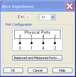
The notation for converted impedance parameters and the functionality of the More Impedances dialog is analogous to the definition of S-parameters.
Z<— selects the type (left pull-down list) and the port number assignment (right pull-down list) of the impedance parameter. Mixed mode parameters are only available if a balanced port configuration is active. They are expressed as Y<mout><min>, where <mout> and <min> denote the output and input port modes. The port numbers are assigned in the order Y<out>< in>, where <out> and <in> denote the output (response) and input (stimulus) port numbers of the DUT.
Balanced and Measured Ports opens the Balanced Port and Port Groups dialog to define the properties of the test ports. Single-ended (unbalanced) impedance parameters are assigned to the physical test ports of the analyzer. Balanced impedance parameters are assigned to logical test ports. Selecting a balanced port configuration with logical test ports means that the unbalance-balance conversion is switched on and that the analyzer provides mixed mode parameters.
The graphics above the Balanced and Measured Ports button illustrates the current port configuration.
 The port configuration
is valid for all traces in the channel
The port configuration
is valid for all traces in the channel
The settings made in the Balanced and Measured Ports dialog are channel settings and therefore apply to all traces assigned to the channel (Balanced and Measured Ports is also accessible through Channel –Mode–Port Config...). Within a channel the analyzer measures either single-ended or mixed mode parameters. If a balanced test port configuration is selected the single-ended parameters assigned to the channel are converted into mixed mode parameters.
Single-ended
and mixed mode parameters
Relation
between impedances and S-parameters
The relation between the generalized (multiport and mixed mode) impedance parameters and the S-parameters is analogous to the 2-port case. For reflection measurements:
and for transmission measurements:
![]()
where Z0i denotes the reference impedance of the analyzer port no. i.
|
Remote control: |
CALCulate<Ch>:PARameter:MEASure "<Trace_Name>", "Z-S11" | "Z-S12" ... Create
new trace and select name and measurement parameter: |
