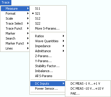
The DC Inputs submenu selects DC voltages or the Power Added Efficiency (PAE) of an active two-port DUT to be measured and displayed.
DC MEAS –1 V...+1 V and DC MEAS –10 V...+10 V select the DC voltages fed to the input connectors DC MEAS as measured quantities.
PAE... opens a dialog to select and configure the PAE measurement.
All DC and PAE measurements use the input connectors DC MEAS at the rear of the instrument. The measurement results are real-valued and displayed as a function of sweep variable (frequency, internal source power, time). The measurements can be performed in parallel to all RF measurements.
Select the DC voltages between pins 6 and 8 of the DC MEAS input connectors as measured quantities. The input connectors are located at the rear panel of the instrument.

The two DC inputs cover different input voltage ranges; see data sheet or rear panel labelling.
The left input connector DC MEAS –1 V...+1 V provides the most accurate measurement for smaller voltages but has a restricted input voltage range.
The right input connector DC MEAS –10 V...+10 V can be used for larger voltages.
|
Remote control: |
CALCulate<Ch>:PARameter:MEASure
"<Trace_Name>", "DC+1V" | "DC+10V"
Create
new trace and select name and measurement parameter: |
Opens a dialog to select the Power Added Efficiency (PAE) of an active 2-port device as measured quantity and to define the parameters for the PAE measurement.
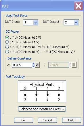
The PAE dialog provides the following settings:
Used Test Ports selects the analyzer port providing the input signal a1 (DUT Input) and the receiver port for the output signal b2 (DUT Output).
The radio buttons and input fields
in the DC Power panel select
the test model and the parameters for measuring
the DC power
PDC supplied
to the DUT. The constants can be incremented with the step size defined
by clicking the  buttons.
Select Topology opens the Port Configuration dialog to define the properties of the test ports. Either physical test ports or logical ports can be used as Input and Output instrument ports. The graphics and messages displayed in the Topology panel are identical to the ones shown in the More S-Parameters dialog. When the unbalance-balance conversion is switched on, the PAE is calculated from the single-ended and differential mode wave quantities (see also Mixed Mode Stability Factors).
 To obtain reasonable results, the test model
and the respective Constant must
be selected in accordance to the test setup.
To obtain reasonable results, the test model
and the respective Constant must
be selected in accordance to the test setup.
 Definition and measurement
of PAE
Definition and measurement
of PAE
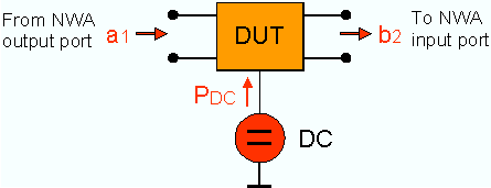
The PAE measurement is based on the standard test setup for forward S-parameter measurements on a 2-port DUT. An additional measurement to determine the supplied power PDC is required.
Definition:
The Power Added Efficiency (PAE) is the ratio of the added RF power generated by an active two-port device (e.g. an amplifier) to the supplied DC power PDC. The added RF power can be expressed as the difference between the power of the outgoing wave b2 at the output of the DUT and the power of the incident wave a1 at the input of the DUT; hence:

Positive PAE values indicate a gain in the RF power, negative values an attenuation. The PAE is always smaller than 1.
|
Remote control: |
CALCulate<Ch>:PARameter:MEASure "<Trace_Name>", "PAE21" | "PAE12" |... Create
new trace and select name and measurement parameter: |
The power PDC supplied
to the DUT can be measured using either one of the DC inputs DC
MEAS  10V (for large voltages), DC
MEAS 1V (for small voltages) or both inputs. The
DC Power panel in the PAE
dialog suggests different models involving different test setups and approximations.
The models are selected by means of the radio buttons in the DC
Power panel; they depend on the properties of the DC power supply
(constant current IDC
or constant power UDC)
and an optional precision resistor R used to measure the DC current. The
values IDC,
UDC, and R determine
the Constants c and k. These
constants must be entered in the DC
Power panel, using the appropriate physical units, before a particular
model can be activated.
10V (for large voltages), DC
MEAS 1V (for small voltages) or both inputs. The
DC Power panel in the PAE
dialog suggests different models involving different test setups and approximations.
The models are selected by means of the radio buttons in the DC
Power panel; they depend on the properties of the DC power supply
(constant current IDC
or constant power UDC)
and an optional precision resistor R used to measure the DC current. The
values IDC,
UDC, and R determine
the Constants c and k. These
constants must be entered in the DC
Power panel, using the appropriate physical units, before a particular
model can be activated.
IDC = const., R = 0 —> PDC = c * U (DC Meas –10 V...+10 V)
UDC = const., R << RDUT, PR = 0 —> PDC = c * U (DC MEAS –1 V...+1 V)
R << RDUT, PR = 0 —> PDC = k * U (DC MEAS –10 V...+10 V) * U (DC MEAS –1 V...+1 V)
UDC = const., PR = U (DC INP2)2/R —> PDC = c * U (DC MEAS –1 V...+1 V) + k * U (DC MEAS –1 V...+1 V)^2
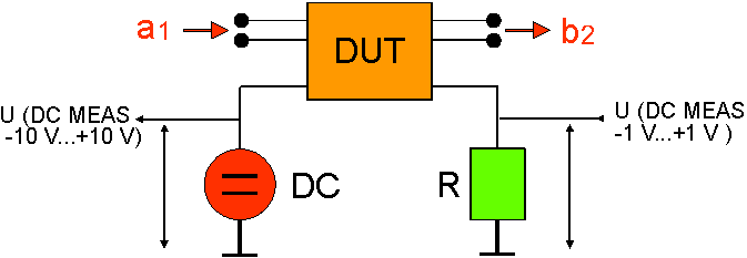
Models 1 and 4 provide the exact DC power supplied to the DUT, the two other models are based on the approximation PR = 0.
|
Remote control: |
[SENSe<Chn>:]PAE:EXPRession |
Opens a configuration dialog for the measurement of wave quantities using an external power meter.
Power
Sensor measurement example
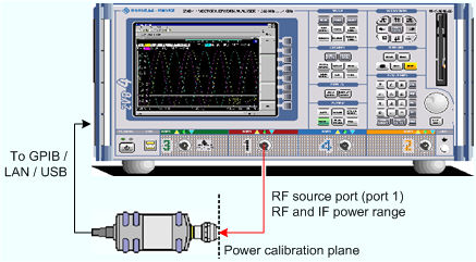
The simplest test setup for a Power Sensor measurement involves one analyzer source port and a power sensor. The power sensor is connected e.g. to the analyzer's USB port and provides the (scalar) wave quantity results.
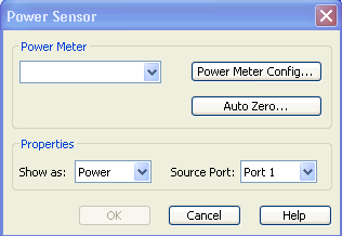
The controls in the Power Meter panel show the configured power meters, open the System Configuration – External Power Meters dialog for adding and configuring external power meters, and start Auto Zeroing for the selected power meter.
Show as selects the physical unit of the displayed trace. It is possible to display the measured Voltage U or convert the wave quantity into an effective power according to P = V2/Re(Z0). Z0 denotes the reference impedance of the source port (for wave quantities an) or of the receive port (for wave quantities bn). The reference impedances are defined in the Port Configuration dialog.
Source Port selects one of the available test ports of the analyzer as a source of the stimulus signal.
Zeroing calibrates the external power sensor by adjusting its reading at zero signal power. For this purpose, the RF power source must be switched off or disconnected from the sensor (see below!). R&S power sensors automatically detect the presence of any significant input power. This aborts zeroing and generates an error message. Zeroing can take a few seconds, depending on the sensor model; refer to the documentation of your external power sensor for more information.
Repeat zeroing
During warm-up after switching on or connecting the instrument
After a substantial change of the ambient temperature
After fastening the power sensor module to an RF connector at high temperature
After several hours of operation
When very low-power signals are to be measured, e.g. less than 10 dB above the lower measurement limit.
Switch off the RF power source for zeroing; do not disconnect it from the power sensor. In this way you will maintain the thermal equilibrium, and zeroing will also compensate for the noise superimposed on the measured signal (e.g. from a broadband amplifier).
A reset of the analyzer does not affect the last zeroing result.
|
Remote control: |
CALCulate<Ch>:PARameter:MEASure "<Trace_Name>",
"Pmtr1D1" | ... Create
new trace and select name and measurement parameter: |
