
The rear panel of the analyzer provides various connectors for external devices and control signals.
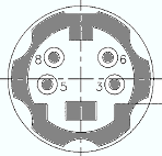
Coaxial BNC connectors used to apply an external DC voltage (bias) to the test ports. The PORT BIAS connectors are numbered 1 to 4 (for four-port analyzers). The internal equivalent circuit is shown in section Direct Generator and Receiver Access.
 Each PORT BIAS input is protected by an exchangeable fuse.
|
Pin No. |
Name |
Input
(I) or |
Voltage Range |
Function |
|
Center conductor |
PORTBIAS1/2/3/4 |
I |
See data sheet |
DC input for test port 1/2/3/4 |
|
Outer conductor |
GNDA |
– |
0 V |
Analog ground |
|
|
Attention! Use double shielded cables at the BNC rear panel connectors and match signal with 50 Ω in order to comply with EMC directives! See also EMI Suppression |
Coaxial bidirectional auxiliary connector that can be wired as needed. The AUX connector is not fitted on standard instruments.
8-pin connector RJ-45 used to connect the analyzer to a Local Area Network (LAN). The pin assignment of the RF-45 connector supports category 6 / 7 UTP/STP (Unshielded/Shielded Twisted Pair) cables.
See also EMI Suppression

For a detailed description refer to section Universal Interface.
|
|
Important note: Use only well shielded cables or disconnect the input pins of the UNIVERSAL INTERFACE connector in order to avoid spurious input signals which may cause undesirable events. |
GPIB bus (IEC/IEEE) connector. For a detailed description refer to section GPIB Bus Interface. See also EMI Suppression
Double Universal Serial Bus connector of type A (master USB), equivalent to the USB connectors at the front panel. See also EMI Suppression
Two inputs for DC measurements. The connectors are of the same type but specified for different input voltage ranges, see data sheet. The DC measurement provides the voltage between pins 6 and 8 of the connectors.
|
Pin No. |
Name |
Input
(I) or |
Function |
|
3 |
GNDA |
- |
Analog ground |
|
5 |
GNDA |
- |
Analog ground |
|
6 |
DCMEAS1VPOS |
I |
Positive 1 V or 10 V DC input |
|
8 |
DCMEAS1VNEG |
I |
Negative 1 V or 10 V DC input |
Coaxial BNC connector used as an input or output for the 10 MHz reference clock signal.

The function of the 10 MHz REF connector depends on the Int. Reference or Ext. Reference setting in the System menu:
If Int. Reference is active, 10 MHz REF is used as an output connector for the 10 MHz internal reference clock signal of the analyzer.
If Ext. Reference is active, 10 MHz REF is used as an input connector for an external 10 MHz reference clock signal. The external reference signal must meet the specifications of the data sheet. The internal reference signal is synchronized to the external signal.
|
Pin No. |
Name |
Input
(I) or |
Voltage Range |
Function |
|
Center conductor |
FR_REF_10_OUT/IN |
B |
See data sheet |
Reference frequency |
|
Outer conductor |
GNDA |
– |
0 V |
Analog ground |
Use double shielded cables at the BNC rear panel connectors
and match signal with 50 Ω in order to comply with EMC directives!
See also EMI
Suppression
15-pole Sub-Min-D connector used to connect and external VGA monitor.
|
Pin No. |
Name |
Input
(I) or |
Voltage Range |
Function |
|
1 |
RED |
O |
75 Ω shielded |
Red signal |
|
2 |
GREEN |
O |
75 Ω shielded |
Green signal |
|
3 |
BLUE |
O |
75 Ω shielded |
Blue signal |
|
4 |
NC |
– |
– |
– |
|
5 |
GNDA |
– |
0 V |
Analog ground |
|
6 |
GNDA |
– |
0 V |
Analog ground |
|
7 |
GNDA |
– |
0 V |
Analog ground |
|
8 |
GNDA |
– |
0 V |
Analog ground |
|
9 |
GNDA |
– |
0 V |
Analog ground |
|
10 |
GNDA |
– |
0 V |
Analog ground |
|
11 |
NC |
– |
– |
– |
|
12 |
DDCDAT |
|
|
|
|
13 |
|
|
|
|
|
14 |
|
|
|
|
|
15 |
|
|
|
|
8-pin RJ-45 connector for future extensions. The CASCADE connector is located between the MONITOR and the USER CONTROL connectors.
 On older instruments the CASCADE connector may be hidden
behind a cover plate. Simply unscrew the plate if you want to use the
connector.
On older instruments the CASCADE connector may be hidden
behind a cover plate. Simply unscrew the plate if you want to use the
connector.
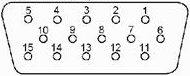
25-pole D-Sub connector used as an input and output for low-voltage (3.3 V) TTL control signals. Some of the USER CONTROL lines can be controlled via GPIB bus (see CONTrol... and OUTPut... subsystems).


|
Pin No. |
Name |
Input
(I) or |
Function |
|
1 |
GNDD |
- |
Digital ground |
|
2 |
EXT TRG |
I |
External trigger signal *) |
|
3 |
GNDD |
- |
Digital ground |
|
4 |
BUSY |
O |
Measurement running, configurable signal (see Define Busy Signal) |
|
5 |
GNDD |
- |
Digital ground |
|
6 |
READY FOR TRIGGER |
O |
Measurement terminated, ready for trigger |
|
7 |
GNDD |
- |
Digital ground |
|
8 |
CHANNEL BIT 0 |
O |
Channel-specific bit 0; |
|
9 |
CHANNEL BIT 1 |
O |
Channel-specific bit 1 |
|
10 |
CHANNEL BIT 2 |
O |
Channel-specific bit 2 |
|
11 |
CHANNEL BIT 3 |
O |
Channel-specific bit 3 |
|
12 |
GNDD |
- |
Digital ground |
|
13 |
PASS 1 |
O |
Pass/fail result of limit check TTL Out Pass 1 |
|
14 |
PASS 2 |
O |
Pass/fail result of limit check TTL Out Pass 2 |
|
15 |
GNDD |
- |
Digital ground |
|
16 |
DRIVE PORT 1 |
O |
Test port 1 is source port (drive port) |
|
17 |
DRIVE PORT 2 |
O |
Test port 2 is source port (drive port) |
|
18 |
DRIVE PORT 3 |
O |
Test port 3 is source port (drive port) |
|
19 |
DRIVE PORT 4 |
O |
Test port 4 is source port (drive port) |
|
20 |
GNDD |
- |
Digital ground |
|
21 |
EXT GEN TRG |
O |
Control signal for external generator |
|
22 |
EXT GEN BLANK |
I |
Handshake signal from external generator |
|
23 |
GNDD |
- |
Digital ground |
|
24 |
FOOT SWITCH 1 |
I |
Control input A |
|
25 |
FOOT SWITCH 2 |
I |
Control input B |
*) Note: Feeding
in the external trigger signal via the BNC connector EXT
TRIGGER
is equivalent.
Both input connectors must not be used simultaneously, because this can
cause malfunctions of the analyzer.
|
|
Important note: Use only well shielded cables or disconnect the input pins of the USER CONTROL connector in order to avoid spurious input signals which may cause undesirable events. This is of particular importance for the external trigger input (pin no. 2) if the EXT TRIGGER input is used. |
Coaxial BNC connector used as an input for a low-voltage (3.3 V) TTL external trigger signal.

*) Note: Feeding in the external trigger signal at pin 2 of the D-Sub connector USER CONTROL is equivalent. Both input connectors must not be used simultaneously, because this can cause malfunctions of the analyzer.
|
Pin No. |
Name |
Input
(I) or |
Voltage Range |
Function |
|
Center conductor |
RP_EXT_TRG |
I |
3.3 V TTL |
External trigger signal |
|
Outer conductor |
GNDA |
– |
0 V |
Analog ground |
Use double shielded cables at the BNC rear panel connectors
and match signal with 50 Ω in order to comply with EMC directives!
See also EMI
Suppression

