The equivalent USB ports on the front and rear panel of the analyzer can be used to connect a variety of accessories:
A mouse simplifies operation of the instrument using the controls and dialogs of the Graphical User Interface (GUI).
A keyboard simplifies the entry of data.
A printer generates hard copies of the screen contents.
In addition the analyzer provides interfaces for monitor connection and network integration:
An external monitor shows the magnified Graphical User Interface (GUI) with all diagram areas and controls.
A LAN connection can be established in order to access the hard disk or control the analyzer from an external PC.
A USB mouse can be connected to one of the Universal Serial Bus connectors on the front panel or on the rear panel (double USB connectors).

The mouse is detected automatically when it is connected. It is safe to connect or disconnect the mouse during the measurement.
 Use the Start
–
Control Panel –
Mouse menu of Windows XP to configure the mouse properties. To
access Windows XP, press the Windows
key on the external keyboard or on the
front panel.
Use the Start
–
Control Panel –
Mouse menu of Windows XP to configure the mouse properties. To
access Windows XP, press the Windows
key on the external keyboard or on the
front panel.
Operating the analyzer does not require a mouse. You can access all essential
functions using the keys on the front panel.
A keyboard can be connected to one of the Universal Serial Bus connectors on the front panel or on the rear panel (double USB connectors).
The keyboard is detected automatically when it is connected. The default input language is English – US. It is safe to connect or disconnect the external keyboard during the measurement.
Use the Start
–
Control Panel –
Keyboard or Regional and Language
Options menu of Windows XP to configure the keyboard properties.
To access Windows XP, press the Windows
key on the external keyboard or on the
front panel.
Operating the analyzer does not require a keyboard. You can access all
essential functions using the keys on the front panel. In combination
with a mouse, the front panel keys provide access to all instrument functions.
A printer can be connected to one of the Universal Serial Bus connectors on the front panel or on the rear panel (double USB connectors).
It is safe to connect or disconnect the printer during the measurement. When printing a copy (File – Print), the analyzer checks whether a printer is connected and turned on and whether the appropriate printer driver is installed. If required, printer driver installation is initiated using Windows XP's Add Printer Wizard. The wizard is self-explanatory. A printer driver needs to be installed only once, even though the printer may be temporarily removed from the analyzer.
A great variety of printer drivers is available on the analyzer. To obtain the complete list, access Windows XP (press the Windows key) and open the Add Printer Wizard in the Start –Control Panel – Printer and Faxes menu.
You can load updated and improved driver versions or new drivers from an installation disk, USB memory stick or another external storage medium. Alternatively, if the analyzer is integrated in a network, you can install driver data stored in a network directory. In either case, use the Add Printer Wizard to complete the installation.
 Use the Page
Setup
dialog or the Start –
Control Panel –
Printers and Faxes menu of Windows XP to configure the printer
properties. To access Windows XP, press the Windows
key on the external keyboard or on the
front panel.
Use the Page
Setup
dialog or the Start –
Control Panel –
Printers and Faxes menu of Windows XP to configure the printer
properties. To access Windows XP, press the Windows
key on the external keyboard or on the
front panel.
A standard VGA monitor or LCD display can be connected to the 15-pole Sub-Min-D MONITOR connector on the rear panel of the analyzer.

|
|
Attention! The monitor must be connected while the instrument is switched off (or in standby mode). Otherwise correct operation can not be guaranteed. |
The monitor displays the magnified analyzer screen with all diagram areas, measurement results and control elements. No extra configuration is required.
With an additional mouse or keyboard connected to the
analyzer, you can control the measurement from the external monitor. If desired, add the Hardkey Bar (front panel key bar) to the analyzer screen.
It is possible to increase the resolution of the external VGA monitor; see Increasing the Monitor Resolution.
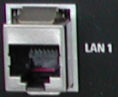
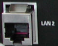
A LAN cable can be connected to one of the LAN connectors on the rear panel of the analyzer. To establish a LAN connection proceed as follows:
Refer to section Assigning an IP Address and learn how to avoid connection errors.
Connect a CAT6 or CAT7 RJ-45 (LAN, Ethernet) cable to one of the LAN ports.
The LAN ports of the analyzer are auto-crossover Ethernet
ports. You can connect them to a network that is equipped with Ethernet
hardware (hub, switch, router), but you can also set up a
direct connection to a computer or another test instrument. For both connection
types, you can use either crossover or standard straight-through Ethernet
cables.
The IP address information is displayed in the Info
– Setup
Info
dialog.
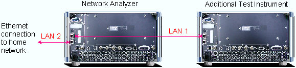
The two LAN connectors on the rear panel of the analyzer are equivalent. With one LAN connector used to establish a connection to a home/company network, the other one can be used to connect an additional instrument, e.g. an additional analyzer or signal generator.
 Defining
the network topology: Router vs. network client
Defining
the network topology: Router vs. network client
With two LAN connections, it is possible to use the analyzer in two alternative ways:
As a client participating in two independent networks, one comprising the home network including the analyzer, the second consisting of the additional test instrument plus the analyzer.
As a data router between the additional test instrument and the home network. This configuration means that the analyzer and the additional test instrument are integrated into a single network.
The network topology is defined in Windows XP's Control Panel –Network Connections – Local Area Connection Status – Local Area Connection Properties – Internet Protocol (TCP/IP) Properties – Advanced TCP/IP Settings dialog. Both instruments must have independent IP addresses; see Assigning an IP Address. Contact your LAN administrator for details.
|
|
Attention! Never use both LAN connectors to connect the analyzer in parallel to the same network as this will result in connection errors. |

