The functions in the Marker menu are used to position markers on a trace, configure their properties and select the format of the numerical readout.
Markers are tools for selecting points on the trace and for numerical readout of measured data. A marker is displayed with a symbol (a triangle, a crossbar or a line) on the trace, which may be a data trace or a memory trace. At the same time, the coordinates are displayed in a marker info field or in a table. Each marker can be defined as a normal marker, reference marker, delta marker or discrete marker.
A (normal) marker(M 1, M 2, ...) determines the coordinates of a measurement point on the trace. Up to 10 different normal markers can be assigned to a trace.
A reference marker(Ref) defines the reference value for all delta markers.
A delta marker(Δ) indicates the coordinates relative to the reference marker.
The stimulus value of a discrete marker always coincides with a sweep point.
A special set of markers M 1 to M 4 is provided for bandfilter search mode.
The most common tasks to be performed with markers can be achieved using the Marker menu functions:
Determine the coordinates of a measurement point on the trace. In polar diagrams where no x-axis is displayed, markers can be used to retrieve the stimulus value of specific points.
Determine the difference between two trace points or the relative measurement result (Delta Mode).
Convert a complex measurement result into other formats.
Markers also play an important role in performing the following advanced tasks:
Change the sweep range and the diagram scale (Marker Funct.).
Search for specific points on the trace (Search).
|
|
|
The Marker menu contains the following functions:
Marker 1/2/3 creates the markers numbered 1, 2, and 3.
Ref. Marker... creates the reference marker which is used to measure relative values and distances.
Delta Mode activates the display of the active marker values relative to the reference marker.
Ref. Marker -> Marker places the reference marker to the position of the active marker.
All Markers Off removes all markers from all traces of the active setup.
Coupled Markers couples the markers on different traces.
Discrete Marker turns the active marker into a discrete marker and vice versa.
More Markers opens a submenu to create the markers numbered 4 to 10.
Marker Format defines an output format for the (complex) marker values.
More Markers opens a submenu to create the markers numbered 4 to 10.
Marker Properties... opens a dialog with extended marker settings.
Export Markers... exports the marker values to an ASCII file.
 Toggle
functions in the Marker menu
Toggle
functions in the Marker menu
Some of the Marker functions toggle between two alternative states when they are pressed repeatedly:
Delta Mode switches the delta mode for the active marker on or off.
Coupled Mkrs activates or deactivates marker coupling.
Marker 1, ..., Marker 10 and Ref. Marker create a marker or remove it from the display. A removed marker remembers its properties (stimulus value, format, delta mode, number) and will be restored with these properties when Marker <n> or Ref. Marker is selected again. The marker properties are definitely lost when the associated trace is deleted.
Markers are available for all diagram types (Trace – Format).
Creates the markers numbered 1, 2, and 3, respectively, and assigns them to the active trace (toggle function). Marker 1/2/3 opens the numeric entry bar to define the marker position (Stimulus M 1/2/3). The default position is the center of the sweep range.

On closing the Stimulus Mkr 1/2/3 numeric entry bar a marker symbol (triangle) labeled M <n> is positioned on the trace and the marker coordinates are displayed in the Info Field.
To select one of several markers as an active marker, do one of the following:
Click the marker symbol.
Click the marker line in the marker info field.
To change the position of the active marker on the trace use one of the following methods:
Drag-and-drop the marker symbol to the desired position.
Click the Marker <n> or Ref. Marker softkey to call up the entry bar for the new stimulus value.
Right-click the diagram area or select Mkr. Propertiesto call up the Marker Properties dialog and select the new stimulus value.
Use the Searchfunctions to place the marker to a specific point on the trace.
 If the marker position is defined explicitly
by entering a numeric value, the marker position can be outside the sweep
range. If it is just varied using the rollkey, the mouse or the cursor
keys, it always remains within the sweep range. If the position of a marker
outside the sweep range is varied, it is automatically moved to the start
or stop value of the sweep range, whichever is closer.
If the marker position is defined explicitly
by entering a numeric value, the marker position can be outside the sweep
range. If it is just varied using the rollkey, the mouse or the cursor
keys, it always remains within the sweep range. If the position of a marker
outside the sweep range is varied, it is automatically moved to the start
or stop value of the sweep range, whichever is closer.
|
Remote control: |
CALCulate<Chn>:MARKer<Mk>[:STATe]
ON
|
Creates a reference marker and assigns it to the active trace (toggle function). Ref. Marker opens the numeric entry bar to define the marker position (Stimulus Ref Mkr). The default position is the center of the sweep range.

On closing the Stimulus Ref Mkr numeric entry bar a marker symbol (triangle) labeled Ref is positioned on the trace and a line indicating R plus the marker coordinates is inserted in the marker info field.
The reference marker defines the reference value for all markers that are in Delta Mode.
|
Remote control: |
CALCulate<Chn>:MARKer<Mk>:REFerence[:STATe]
ON
|
Converts the active marker to a delta marker so that its values are measured and indicated relative to the reference marker (toggle function). A Δ sign placed in front of the marker line indicates that the marker is in Delta Mode.
The reference marker itself can not be set to delta mode but must be present when another marker is set to delta mode. The analyzer takes into account these conditions when Delta Mode is selected:
If Delta Mode is selected while the reference marker is active, the marker in the info list after the reference marker is activated and set to delta mode. If the current trace contains the reference marker only, a new M 1 is created and set to delta mode.
If Delta Mode is selected for a normal marker while the current trace contains no reference marker, a reference marker is created.
A delta marker is required to set the sweep
span using marker functions (Span
= Marker).
|
Remote control: |
Places the reference marker to the position of the active marker. Ref. Marker -> Marker is not active if the active marker is a reference marker.
|
Remote control: |
– |
Removes all markers from the active trace. Markers on other traces are not affected. The removed markers remember their properties (stimulus value, format, delta mode, number) when they are restored. The marker properties are definitely lost when the associated trace is deleted.
|
Remote control: |
Couples the markers of all traces in the active setup to the markers of the active trace (toggle function). While marker coupling is active, the active trace markers assume the role of master markers; the other markers behave as slave markers, following any change of position of the master marker.
The concept of marker coupling means that corresponding markers on different traces (i.e. markers with the same number or reference markers) are positioned to the same stimulus values but keep their independent format and type settings. When a trace with markers is selected as the active trace and marker coupling is switched on, the following happens:
The active trace and all associated markers are left unchanged. The active trace markers become the master markers of the setup.
Markers on the other traces which have no corresponding master marker are removed but remember their properties and can be re-activated after the coupling is released.
The remaining markers on the other traces become slave markers and are moved to the position of the corresponding master markers. "Missing" slave markers are created so that each trace has the same number of markers placed at the same position.
If the position of a master marker
is outside the sweep range of the slave trace, the slave marker is displayed
at the edge of the diagram. The marker info field indicates an invalid
measurement result: 
While marker coupling is active, it is possible to:
Move a master marker and thus change the position of all corresponding slave markers.
Activate another trace in order to make the associated markers the new master markers.
Marker coupling makes sense only if the master and the
slave traces use the same stimulus variable. Channels with a different
stimulus variable (sweep
type)
are not coupled.
|
Remote control: |
Turns the active marker into a discrete marker and vice versa.
 The stimulus value of a discrete marker always coincides
with a sweep point. Use discrete markers in order to avoid that the marker
indicates an interpolated measurement value.
The stimulus value of a discrete marker always coincides
with a sweep point. Use discrete markers in order to avoid that the marker
indicates an interpolated measurement value.
|
Remote control: |
CALCulate<Chn>:MARKer<Mk>:MODE |
Opens a submenu to select an output format for the (complex) active marker value in the marker info field. The default marker format is the format of the associated trace. The current format is indicated with a l.
All marker formats are available irrespective of the measured quantity. The output values are calculated by a simple conversion of a complex measurement result, where the marker format defines the conversion rules. This flexibility in the calculation must be kept in mind when interpreting the results and physical units displayed; see also Measured Quantities and Display Formats.
Short
description of marker formats
The formats of the markers assigned to a trace are independent of each other and of the trace format settings. The following table gives an overview on how a complex marker value z = x + jy is converted.
|
Marker Format |
Description |
Formula |
|
dB Mag |
Magnitude of z in dB |
|z| = sqrt ( x2
+ y2 ) |
|
Lin Mag |
Magnitude of z, unconverted |
|z| = sqrt ( x2 + y2 ) |
|
Phase |
Phase of z |
φ (z) = arctan (y/x) |
|
Real |
Real part of z |
Re(z) = x |
|
Imag |
Imaginary part of z |
Im(z) = y |
|
SWR |
(Voltage) Standing Wave Ratio |
SWR = (1 + |z|) / (1 – |z|) |
|
Delay |
Group delay, neg. derivative of the phase response*) |
– d φ (z) / d ω |
|
dB Mag and Phase |
Magnitude of z in dB and phase in two lines |
20 * log|z| dB |
|
Lin Mag and Phase |
Magnitude of z (unconverted) and phase in two lines |
|z| |
|
Real and Imag |
Real and imaginary part of z in two lines |
x |
|
Default (Trace) |
Marker format identical with trace format |
– |
|
R + j X |
Unnormalized resistance and reactance; L or C in three
lines |
R |
|
G + j B |
Unnormalized conductance and susceptance; L or C in three
lines |
G |
*) The delay aperture is defined in the Trace – Format menu.
**) The equivalent inductances or capacitances L or C are calculated from the imaginary part of the impedance according to
|
Remote control: |
Opens a submenu to create the markers numbered 4 to 10. The markers are analogous to marker no. 1 to 3.
|
Remote control: |
Opens a dialog to define the properties of all markers of the active trace.
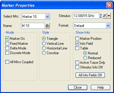
In the left part the dialog contains four input fields and drop-down lists to select a marker and define the basic properties of a selected marker which is switched on in the Mode panel.
The Mode panel contains check boxes to select properties that are related to the marker positions. All properties can be combined.
Style defines how the selected marker is displayed on the screen.
Show Info selects the marker info to be displayed at the Marker Position, in the marker info field or in a separate Table below the diagram area. The display options may be selected simultaneously or all switched off. The table provides more information than the marker info field:
Calls up a Save As... dialog to store the current marker values to a marker file.
The analyzer uses a simple ASCII format to export marker values. By default, the marker file extension is *.txt. The file contains all traces in the active setup together with their names and measured quantities. Below each trace, the file shows a list of all markers with their names, stimulus and response values.
The following example of a marker file describes a setup with two traces Trc1 and its memory trace. Trc1 has no markers assigned, the memory trace has four markers named M 1, ..., M 4.
|
Remote control: |