The commands in the second section of the Lines submenu define the ripple test. A ripple test is a special type of limit test where the maximum difference between the largest and the smallest response value of the trace must not exceed the specified limit. This test is suitable e.g. to check whether the passband ripple of a filter is within acceptable limits, irrespective of the actual transmitted power in the passband. See also background information for Limit Lines.
|
|
|
Define Ripple Test... opens a dialog to define, save or recall ripple limits.
Show Ripple Limits displays or hides the ripple limit line associated to the active trace.
Ripple Check activates or deactivates the ripple limit check.
Show All Ripple Results shows or hides the info field for all traces in the active setup, irrespective of the active trace.
Global Beep activates or deactivates the acoustic signal indicating a limit or ripple limit excess.
Global Check activates a global (composite) limit and ripple limit check on all traces in the active setup.
TTL Out Pass 1/2 activates or deactivates a TTL output signal at the USER CONTROL connector indicating whether the trace was passed or failed.
Horizontal Line... displays or hides the horizontal line of the active trace and changes its position.
Ripple limit lines are available for all Cartesian diagram types (Trace – Format). For polar diagrams, the functions of the ripple check (except the Global Check) are grayed. The limit lines are hidden and the ripple limit check (except the global check) is disabled when a Cartesian trace format is replaced by a polar diagram.
Opens a dialog to define the ripple limits for the active trace on a range-by-range basis. A separate ripple limit can be assigned to each range.
 Defining
ripple limits with minimum effort
Defining
ripple limits with minimum effort
Choose one of the following methods to efficiently create and handle ripple limit ranges:
To configure a limit test with only a few ranges, use Add Range and edit each range in the table individually.
Use the Align All Ranges button to create non-overlapping, contiguous ranges of equal width.
Use the multiselection feature to edit several ranges at the same time.
Save your ripple ranges to a file so you can re-use or modify them in later sessions (Save Ripple Limit..., Recall Ripple Limit...).
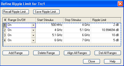
The Define Ripple Limit dialog contains a table to edit the individual ripple check ranges; see below. The active trace is indicated in the title bar of the dialog. The buttons below the table extend, shorten, or re-order the range list.
The buttons to the right of the table are used to import and export limit line data.
To import a ripple limit file (*.ripple) you can also
use the Windows Explorer and simply double-click the file or drag and
drop the file into the NWA application. You have to switch on the limit
check separately. Use the paste
marker list
for convenient entry of Start
and Stop
values.
 Columns
in the range table
Columns
in the range table
The table contains an automatically assigned current number for each range plus the following editable columns:
Range On/Off indicates whether the ripple limit check in the range is enabled (On) or Off. Switching off the ripple limit check does not delete the range but hides the entry in the info field.
Start Stimulus is the smallest stimulus (x-axis) value of the range.
Stop Stimulus is the largest stimulus (x-axis) value of the range.
Ripple Limit is the maximum allowed difference between the largest and the smallest trace value in the range.
The ripple limit range is displayed as two parallel, horizontal lines in the diagram. Stop Stimulus –Start Stimulus is the length of both lines; Ripple Limit is their distance; see Rules for Limit Line Definition.
|
Remote control: |
CALCulate<Chn>:RIPPle:CONTrol:DOMain |
In the Define Ripple Limit dialog it is possible to edit several limit ripple ranges at the same time. Selection of one or more ranges (use the left mouse key and the Shift key of an external keyboard) and a right-click on the dark grey Seg. area opens a context menu:
The context menu provides the following functions:
Modification of all entries in the range table: Range On/Off, stimulus start and stop values, ripple limit.
Definition of an offset for response and stimulus values in analogy to the Properties of Imported Ranges dialog.
Delete the selected ranges.
Merge the selected ranges to a single new range.
|
Remote control: |
The analyzer places very few restrictions on the definition of ripple limit ranges. The following rules ensure a maximum of flexibility:
Ranges do not have to be sorted in ascending or descending order (e.g. the Start Stimulus value of range no. n doesn't have to be smaller than the Start Stimulus value of range no. n+1).
Overlapping ranges are allowed. The limit check in the overlapping area is related to the tighter limit (the pass test involves a logical AND operation).
Gaps between ranges are allowed and equivalent to switching off an intermediate ripple limit range.
Ripple limit ranges can be partially or entirely outside the sweep range, however, the limits are only checked at the measurement points.
The following figure shows a ripple limit test involving 3 ranges.
As a consequence of the limit line rules, the limit check will always pass a DUT if no limit lines are defined.
The analyzer uses a simple ASCII format to export ripple limit data. By default, the ripple limit file has the extension *.ripple and is stored in the directory shown in the Save Ripple Limit and Recall Ripple Limit dialogs. The file starts with a preamble containing the channel and trace name and the header of the range list. The following lines contain the entries of all editable columns of the list.
Example
of a ripple limit file
The ripple limit list:
is described by the ripple limit file:
|
Remote control: |
MMEMory:LOAD:RIPPle
"Trc_name","file_name"
|
Shows or hides the ripple limit lines associated with the active trace in a Cartesian diagram area. A checkmark appears next to the menu item when the limit line is shown.
The vertical positions of the ripple lines are re-calculated after each sweep; only their stimulus range and distance (the ripple limit) is fixed. The limit line colors are defined in the Define User Color Scheme dialog (Display – Display Config. – Color Scheme...).
 Display of the ripple limits and limit check
are independent of each other: Hiding the limits does not switch off the
limit check.
Display of the ripple limits and limit check
are independent of each other: Hiding the limits does not switch off the
limit check.
|
Remote control: |
Switches the ripple limit check of the active trace on or off. A checkmark appears next to the menu item when the limit check is enabled.
When the limit check is switched on, an info field shows the pass/fail information and the measured ripple in each ripple limit range, and a PASS or FAIL message for the entire active trace is displayed in the center of the diagram. If the limit check fails in a particular ripple line range, the trace within the range can change its color. The Limit Fail Trace color is defined in the Define User Color Scheme dialog (Display – Display Config. – Color Scheme...). An acoustic signal (Global Beep) and a TTL signal indicating pass or fail can be generated in addition.
Ripple limit check and display of the limit
lines are independent of each other: With disabled limit check, the limit
line can still be displayed.
If no limit lines are defined for the active trace, the limit check can
be switched on but will always PASS
the trace.
|
Remote control: |
CALCulate<Chn>:RIPPle:STATe
ON | OFF |
Shows or hides the info field for all traces in the active setup, irrespective of the active trace. If Show Result All Traces is disabled (and the ripple check is on), the info field covers the active trace only.
|
Remote control: |
No direct equivalent (display configuration) |
Activates or deactivates the fail beep. The fail beep is a low-tone acoustic signal that is generated each time the analyzer detects an exceeded limit. No fail beep can be generated if the limit check is switched off. A checkmark appears next to the menu item when the fail beep is enabled.
|
Remote control: |
Activates or deactivates the global limit check including upper/lower limits and ripple limits. The global limit check is a composite limit check over all traces of the current setup. The result of the global check appears in a popup box whenever Global Limit Check is pressed.
 or
or 
PASS represents pass for all traces with enabled limit check. A trace without limit lines or with disabled individual limit check always passes the global check.
FAIL means that the limit check for one or more traces failed.
|
Remote control: |
Assigns the active trace to the low-voltage (3.3 V) TTL output signals at the USER CONTROL connector. To select TTL Out Pass 1 / 2, the limit check of the active trace must be switched on.
If TTL Out Pass 1 is selected and the active trace passes the limit check (including upper/lower limits and ripple limits), then the TTL signal is applied to pin 13 of the USER CONTROL connector.
If TTL Out Pass 2 is selected and the active trace passes the limit check (including upper/lower limits and ripple limits), then the TTL signal is applied to pin 14 of the USER CONTROL connector.
If the active trace exceeds the limits, then no TTL signal is generated. It is possible to activate both pass/fail signals for the same trace or assign several traces to a signal.
Extension:
Monitoring several traces
If a channel contains several traces, is possible to assign them one after another to each pass/fail signal. The procedure divides the traces of the channel into four groups that are either assigned to signal 1, to signal 2, to both signals, or to none of them.
If several traces with independent limit check are assigned to a pass/fail signal, then the TTL signal is generated only if all traces are within limits. It is switched off as soon as one trace exceeds the limits.
Application:
Graduated limit check
The two pass/fail signals can be used to distinguish three quality levels of a DUT. The test is performed with a looser and a tighter set of limit lines that are assigned to two traces with identical channel and trace settings. The limit check for the two traces is monitored by means of the signals TTL Out Pass 1 /TTL Out Pass 2, respectively.
If the DUT is passed in both limit checks, the quality is good.
If the DUT is failed in the limit check with tighter limits, the quality is still sufficient.
If the DUT is failed in both limit checks, the quality is poor.
Instead of using two traces, it is possible to consider two groups of traces that are assigned to TTL Out Pass 1 and TTL Out Pass 2.
|
Remote control: |
Shows or hides the horizontal line associated to the active trace in a Cartesian diagram area. A checkmark appears next to the menu item when the horizontal line is shown.
The horizontal line (or display line) is a red line which can be moved to particular trace points in order to retrieve the response values.
Pressing Horizontal Line for a first time shows the line for the active trace and opens the numeric entry bar to define its position (response value). The (rounded) position is displayed near the left edge of the screen.
Pressing Horizontal Line for a second time hides the horizontal line for the active trace.
Use the analyzer's
drag-and-drop functionality to move the horizontal line symbol to the
desired position.
|
Remote control: |


