The Trace Funct(ions) store traces to the memory and perform mathematical operations on traces
 Refer to section Trace
Types
to learn more
about data traces, memory traces, and mathematical traces.
Refer to section Trace
Types
to learn more
about data traces, memory traces, and mathematical traces.
|
|
|
Data -> Mem stores the active data trace as a memory trace.
Math = Data/Mem activates the mathematical mode where the data trace is divided by the memory trace.
Show Data shows or hides the active data trace.
Show Mem shows or hides the active memory trace.
More Mem opens a submenu to store traces as memory traces, show or hide traces.
Math = User Def activates the mathematical mode with a user-defined relation between traces.
User Def Math... opens a dialog to define a mathematical relation between traces.
Transform opens a submenu with the time domain transformation functions (with option ZVAB-K2, Time Domain).
Trace Statistics opens a submenu to evaluate statistical and phase information of the trace.
Smoothing On activates the smoothing function for the active trace.
Smoothing Aperture... defines how many measurement points are averaged to smooth the trace.
Import/Export Data stores the active trace to a file or loads a memory trace from a file.
Shift Response Value... opens a dialog to define a user-correction to the measured values.
Shift Stimulus Value... shifts a memory trace in horizontal direction.
Max Hold On enables or disables the max hold (peak hold) function for the active trace.
Min Hold On enables or disables the min hold function for the active trace.
Restart Hold restarts the max hold (peak hold) or min hold function for the active trace, discarding the old maximum or minimum measurement results.
Linearity Deviation opens a submenu to compensate the active trace for the average slope and response value in order to show the deviation from linearity.
Many of the functions of the Trace Funct menu act on the active trace. Data traces and the associated memory traces share many of their properties; see coupling of memory traces.
Stores the current state of the active trace as a memory trace. The memory trace is displayed in the active diagram area with another color, and its properties are indicated in the trace list:
Memory traces are named Mem<n>[<Data_Trace>] where <n> counts all data and memory traces in the active setup in chronological order, and <Data_Trace> is the name of the associated data trace. Trace names can be changed in the Trace Manager dialog.
The exact function of Data -> Mem depends on the number of memory traces associated to the active data trace:
If no memory trace is associated with the active trace, a new memory trace is generated.
If several memory traces are associated with the active trace, the current measurement data overwrites the last generated or changed memory trace.
 To store the current measurement data to a new memory
trace (without overwriting an existing memory trace), or select and overwrite
a particular memory trace, use the ->
Mem
dialog. You can also create multiple memory traces using the Import
Data
dialog. Notice that it is not possible to store Max.
Hold
traces to memory.
To store the current measurement data to a new memory
trace (without overwriting an existing memory trace), or select and overwrite
a particular memory trace, use the ->
Mem
dialog. You can also create multiple memory traces using the Import
Data
dialog. Notice that it is not possible to store Max.
Hold
traces to memory.
Coupling
of data and memory traces
When a memory trace is generated from a data trace, it is displayed in the same diagram area and inherits all channel and trace settings from the data trace.
The following display settings of a data trace and the associated memory traces are fully coupled. Changing a property of one trace affects the properties of all other traces.
All settings in the Trace – Format menu
All settings in the Trace – Scale menu
Selection of the measured quantity (Trace – Measure) is possible for the data trace but disabled for the memory traces.
Channel settings made for a memory trace act on the associated data trace. Some of the channel settings for a data trace (e.g. the Stimulus range) also affect the display of the memory traces.
 If the sweep type of a data trace is changed so that
the stimulus ranges of the data traces and the memory traces become incompatible,
all coupled memory traces are removed from the diagram area and deleted.
If the sweep type of a data trace is changed so that
the stimulus ranges of the data traces and the memory traces become incompatible,
all coupled memory traces are removed from the diagram area and deleted.
|
Remote control: |
Activates the mathematical mode where the active data trace is divided by the last generated memory trace. The division is calculated on a point-to-point basis: Each measurement point of the active trace is divided by the corresponding measurement point of the memory trace. The result of the division is a mathematical trace and replaces the active data trace in the diagram area. The mathematical trace is updated as the measurement goes on and the analyzer provides new active trace data.
This function is disabled unless a memory trace is coupled to the active data trace. Trace coupling ensures that the two traces have the same number of points so that the mathematical trace Data/Mem is well-defined.
Math = Data/Mem and Math = User Def are alternative options
of the mathematical mode. Selecting one option disables the other. The
mathematical expression defined via User
Def Math
is not affected.
|
Remote control: |
CALCulate<Chn>:MATH[:EXPRession]:SDEFine
<string> |
Displays or hides the active data trace in the diagram area. If one of the mathematical options Math = Data/Mem or Math = User Def are active, then the active mathematical trace is displayed or hidden.
|
Remote control: |
Displays or hides the active memory trace in the diagram area or the memory trace associated with the active data trace.
If no memory trace is associated with the active data trace, Show Mem is disabled.
If several memory traces are associated with the active data trace (see -> Mem), Show Mem affects the last generated or changed memory trace.
|
Remote control: |
Opens a submenu to store traces as memory traces, show or hide traces. The submenu complements the Data -> Mem menu commands.
Data —> Mem opens a dialog to store the active trace to a memory trace.
All Data —> Mem opens a dialog to store all traces in the active setup to memory traces.
The remaining functions hide or show all data traces or memory traces. Moreover it is possible to delete all memory traces in the active setup.
|
Remote control: |
TRACe:COPY
<memory_trc>, <data_trc> (copy data trace to memory
trace) |
The Data -> Mem dialog stores the active trace to a memory trace.
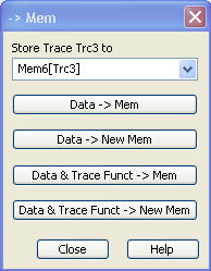
Store Trace <trace_name> to contains all memory traces associated with the active data trace. The selected memory trace can be replaced.
Data -> Mem stores the active data trace to the memory trace selected above. If no memory trace is associated with the current trace, then a new memory trace is created. The new trace is named Mem<n+1>[<Data_Trace>], where n is the largest of all existing memory trace indices.
Data -> New Mem stores the active data trace to a new memory trace, leaving the existing memory traces unchanged.
Data & Trace Funct. -> Mem stores the current state of the active data trace modified by the trace functions to the memory trace selected above. If no memory trace is associated with the current trace, then a new memory trace is created.
Data & Trace Funct. -> New Mem stores the current state of the active data trace modified by the trace functions to a new memory trace, leaving the existing memory traces unchanged.
The trace functions comprise the following mathematical operations:
Any mathematical relation applied to the trace (Math = Data/Mem, Math = User Def).
A shift of the trace in horizontal or vertical direction (Shift Response Value, Shift Stimulus Value).
Data —> Mem and Data —> NewMem store the raw trace without the trace functions, Data & Trace Funct —> Mem and Data & Trace Funct —> NewMem store the trace after it has been transformed using the trace functions.
|
Remote control: |
TRACe:COPY
<memory_trc>,<data_trc>
|
The All Data -> Mem dialog stores all traces in the active setup to memory traces.
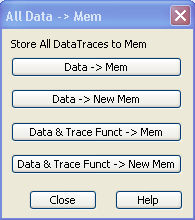
Data -> Mem stores all data traces in the current setup to memory traces. If no memory trace is associated with a data trace, then a new memory trace is created. The new trace is named Mem<n+1>[<Data_Trace>], where n is the largest of all existing memory trace indices. If several memory traces are associated with a data trace, the newest memory trace is replaced.
Data -> New Mem stores all data traces in the current setup to memory traces, leaving the existing memory traces unchanged.
Data & Trace Funct. -> Mem stores the current state of all data traces modified by the trace functions to memory traces. If a trace has no memory trace, then a new memory trace is created.
Data & Trace Funct. -> New Mem stores the current state of all data traces modified by the trace functions to new memory traces, leaving the existing memory traces unchanged.
The trace functions comprise the following mathematical operations:
Any mathematical relation applied to the trace (Math = Data/Mem, Math = User Def).
A shift of the trace in horizontal or vertical direction (Shift Response Value, Shift Stimulus Value).
Data —> Mem and Data —> NewMem store the raw trace without the trace functions, Data & Trace Funct —> Mem and Data & Trace Funct —> NewMem store the trace after it has been transformed using the trace functions.
|
Remote control: |
TRACe:COPY
<memory_trc>,<data_trc>
|
Activates the mathematical mode and displays the mathematical trace defined via User Def. Math. The mathematical trace replaces the active data trace in the diagram area; it is updated as the measurement goes on and the analyzer provides new active trace data.
This function is disabled unless a user-defined mathematical trace is available.
Math = User Def and Math = Data/Mem are alternative options
of the mathematical mode. Selecting one option disables the other. The
mathematical expression defined via Define
Math
is not affected.
|
Remote control: |
CALCulate<Chn>:MATH[:EXPRession]:SDEFine
<string> |
Opens a dialog to define a mathematical relation between traces and calculate a new mathematical trace. Each measurement point of the active trace is replaced by the corresponding point of the mathematical trace.
Compatibility
between traces in mathematical relations
Mathematical traces are either constant functions or functions of one or more data or memory traces. They are calculated on a point-to-point basis. Each trace point no. i of the mathematical trace is calculated from a set of constant values c1, ..., cn plus the trace points Trc1i, Trcmi of all traces 1 to m in the mathematical relation:
Mathi = Fct. (c1, ..., cn, Trc1i, Trcmi ), i = 1, no. of points
Different traces can be used in the same mathematical relation provided that they contain the same number of points. The analyzer places no further restriction on the compatibility of traces, e.g. the sweep points of the traces do not have to be the same.
The number of points belongs to the channel settings. Coupled data and memory traces are always compatible because they have the same channel settings.
The analyzer processes only numeric values
without units in the mathematical formulas. No consistency check for units
is performed.
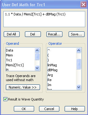
In its upper part the dialog contains a window to view and edit the mathematical expression and four buttons:
To import a math
file (*.mth) you can also use the Windows Explorer and simply double-click
the file or drag and drop the file into the NWA application. You must
enable the mathematical mode separately.
The operands and operators in the expression can be selected from two lists and the Numeric Value panel:
Contains operators for arithmetic operations and mathematical functions. The following table lists how the operators act on a complex quantity z = x + jy.
|
+, -, *, / |
Basic arithmetic operations |
|
() |
Grouping parts of an expression |
|
linMag |
|z| = sqrt ( x2 + y2 ) |
|
dBMag |
dB Mag(z) = 20 * log|z| dB |
|
Arg |
Phase φ (z) = arctan ( Im(z) / Re(z) ) |
|
Re, Im |
x, y (Real and Imag) |
|
log, ln |
Common (base 10) or natural (base e) logarithm |
|
Min, Max |
Smaller or larger values of all points of two traces, e.g. Min(Trc1,Trc2) |
|
StimVal |
Stimulus value*) |
|
tan, atan, sin, asin, cos, acos |
Direct and inverse trigonometric functions. |
*) The function StimVal can be used for all sweep types. Please note that - as with all user math operands - only the numerical value without unit is processed in the user math formula.
In frequency sweeps StimVal provides the stimulus frequency in Hz.
In power sweeps, StimValprovides the voltage in V that results from the source power in dBm. To obtain the correct source power in dBm (for dB Mag trace format), Result is Wave Quantity must be enabled. Note that, due to the conversion into a dBm value, the source power depends on the reference impedance of the port associated with the measured wave quantity, to be set in the Port Configurationdialog.
In time sweeps, StimVal is the stimulus time in s.
In CW mode sweeps, StimVal is the number of the point.
extends the Define Math dialog and opens the numeric input panel (toggle function):
The numeric input panel supports the entry of numeric values and constants. In addition to the numbers 0 to 9, the decimal point and the constants j (complex unit), pi (approx. 3.14159) and e (approx. 2.71828), it contains the following buttons:
+/- changes the sign
Exp defines a number in exponential representation, e.g. 12 exp 3 for 12*10^3 = 12000.
Products of numbers and constants may be entered in abbreviated form, e.g. 2e for 2*e.
If traces are used as operands, the unmodified,
linear complex trace data (no
dB-values) enter into the mathematical expression, irrespective of the
current trace format. No mathematical traces are available as operands.
Result is Wave Quantity in the lower part of the dialog controls the conversion and formatting of the mathematic expression.
If Result is Wave Quantity is enabled the analyzer assumes that the result of the mathematical expression represents a voltage. Examples for voltage-type expressions are all terms proportional to a wave quantity (e.g. 1.1*Data, if a wave quantity is measured) or to a stimulus value of a power sweep. If Show As: Power is selected in the More Wave Quantities dialog, the result is converted into a linear power before the selected trace format is applied. Otherwise no conversion is performed, and dB Mag results are referenced to 1 μV.
If Result is Wave Quantity is disabled the analyzer assumes that the result of the mathematical expression is dimensionless. Examples for dimensionless expressions are all terms proportional to ratios of wave quantities, e.g. Data / Mem2[Trc1]. The selected trace format is applied without previous conversion.
Result is Wave Quantity acts on the result of the mathematical expression only. Wave quantities and power sweep stimulus values always enter into the expression as voltages.
Effect
of Result is Wave Quantity and numeric example
In the More Wave Quantities dialog, the Show as: control element specifies whether wave quantities are displayed as voltages or equivalent powers, using the port impedances for a conversion between the two representations. Result is Wave Quantity is relevant for mathematical traces displayed in units of dBm (Show as: Power and trace format dB Mag):
If Result is Wave Quantity is on (checked), the mathematical trace values <W> are interpreted as voltages and first converted into equivalent powers (<W> —> <P> = <W>2/Re(Z0)). Results in dB Mag format are calculated according to <P>log = 10 * log (<P>/1mW).
If Result is Wave Quantity is off, the mathematical trace values <W> are interpreted as dimensionless quantities. Results in dB Mag format are calculated according to <W>log = 20 * log (<W>).
Example: A mathematical trace value amounts to 1 (real value); the port impedance is 50 Ω. If Result is Wave Quantity is on, the analyzer assumes the trace value to be 1 V, which is converted into a linear power of 20 mW, corresponding to approx. 13 dBm. With Result is Wave Quantity off, the trace value 1 is directly converted into a logarithmic power of 0 dBm.
See also example for CALCulate<Chn>:MATH:WUNit:STATe
ON | OFF.
 Comparing
two traces displayed in dB Mag format
Comparing
two traces displayed in dB Mag format