The Trace Select submenu provides functions to handle traces and diagram areas, and assign traces to channels.
|
|
|
Next Trace selects the next trace as the active trace (disabled if only one trace is defined).
Select Trace opens a box to select an arbitrary trace of the active setup as the active trace (disabled if only one trace is defined).
Add Trace creates a new trace in the current diagram area.
Add Trace + Diag. Area generates a new trace in a new diagram area.
Delete Trace deletes the active trace.
Assign Channel assigns the active trace to another channel.
Assign Diag. Area assigns the active trace to another diagram area.
Trace Manager opens a dialog to perform the previous actions systematically for all traces and diagram areas.
The screen can display several diagram areas simultaneously, each with a variable number of traces.
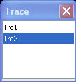
In an active diagram area one of these traces is the active trace. The active trace is highlighted in the trace list on top of the diagram area (Trc 3 in the figure below):
If an inactive area is selected as the active area, the trace that was active last time when the area was active will again become the active trace. It is highlighted in the trace list of the inactive diagram area as shown for Trc6 in the figure below:
All settings in the Trace menu except the Trace Functions involving a memory trace apply to the active trace in the active diagram area.
 In remote control each channel can contain
an active trace. The active remote traces and the active manual trace
are independent of each other; see Active
Traces in Remote Control.
In remote control each channel can contain
an active trace. The active remote traces and the active manual trace
are independent of each other; see Active
Traces in Remote Control.
Selects the next trace in a series of displayed traces as the active trace. This function is disabled if only one trace is defined.
Next Trace has the following meaning:
In a list of traces displayed in a common diagram area, the next trace is the trace below the current trace (in the figure above, Trc 3 is the active trace and Trc 4 is the next trace).
If the active trace is the last trace in the list, the next trace is the first trace in the trace list of the next diagram area.
|
Remote control: |
The numeric suffix <Chn> appended to the first-level mnemonic of a command selects a trace as active trace. |
Opens a box to select an arbitrary trace of the active setup as the active trace. This function is disabled if only one trace is defined.
|
Remote control: |
The numeric suffix <Chn> appended to the first-level mnemonic of a command selects a trace as active trace. |
Creates a new trace in the current diagram area and assigns it to the current channel. The new trace is created with the trace and channel settings of the former active trace but displayed with another color. The former and the new active trace are superimposed but can be easily separated, e.g. by changing the Reference Position.
The new trace is named Trc <n>, where <n> is the largest of all existing trace numbers plus one. The name can be changed in the Trace Manager.
 To
create a new trace in a new channel, use Channel – Channel Select
– New
Channel.
To
create a new trace in a new channel, use Channel – Channel Select
– New
Channel.
|
Remote control: |
CALCulate<Ch>:PARameter:SDEFine
<Trace Name>, < Meas Parameter>
|
Creates a new trace in a new diagram area and assigns the trace to the current channel. The new trace is created with the trace and channel settings of the former active trace but displayed with another color.
The new trace is named Trc <n>, where <n> is the largest of all existing trace numbers plus one. The name can be changed in the Trace Manager.
|
Remote control: |
CALCulate<Ch>:PARameter:SDEFine
<Trace Name>, < Meas Parameter>
|
Deletes the current trace and removes it from the diagram area. Delete Trace is disabled if the setup contains only one trace: In manual control, each setup must contain at least one diagram area with one channel and one trace.
To restore a trace that was unintentionally deleted, use
Undo.
|
Remote control: |
Assigns the active trace to another channel. A popup window offers a list of all channels available:
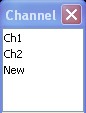
Selecting one of the existing channel names assigns the current trace to the existing channel.
Selecting New creates a new channel and assigns the current trace to the new channel. The new channel is named Ch <n>, where <n> is the largest of all existing channel numbers plus one. The name can be changed in the Channel Manager.
Assign Channel is
disabled if the current setup contains only one channel. To create an
additional channel, select Channel – Channel Select
– New
Channel.
|
Remote control: |
CALCulate<Ch>:PARameter:SDEFine <Trace Name>, < Meas Parameter> |
Assigns the active trace to another diagram area. A popup window offers a list of all areas available:
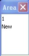
Selecting one of the existing area numbers assigns the active trace to the existing diagram area: The active trace is removed from the previous area and displayed in the new diagram area.
Selecting New creates a new diagram area and assigns the active trace to the new area. The new area is numbered <n>, where <n> is the largest of all existing area numbers plus one.
Assign Diag. Area
is disabled if the current setup contains only one area. To create
an additional area, click Display – Area Select
– New
Diag. Area.
To
go to another diagram area and activate the last active trace in this
area, simply click a point inside the new area.
|
Remote control: |
Opens a dialog to perform the actions in the Trace Select menu systematically for all traces and diagram areas.
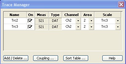
All existing traces of the current setup are listed in a table with several editable (white) or non-editable (gray) columns. Below the table the Trace Manager provides the following buttons:
Add/Delete... opens a dialog to add a new trace or delete a trace.
Coupling opens a dialog to define coupling criteria (channel, scale) for all traces in the table.
Sort Table opens a dialog to change the order of the traces (rows) in the table.
 Columns
in the Trace
Manager table
Columns
in the Trace
Manager table
Name indicates the current trace name. The default names for new traces are Trc<n> where <n> is a current number. Current numbers in the trace names are necessary to make automatic assignments, e.g. decouple the channel settings in the Couplingdialog. To serve as an unambiguous reference, trace names must be unique across all channels and diagram areas.
On indicates whether the trace is displayed on the screen (On) or invisible.
Meas indicates the measured parameter.
Type indicates whether the trace is a data trace(DAT), displaying the current measurement data, or a memory trace(MEM).
Channel indicates the channel of each trace.
Area indicates the diagram area of each trace.
Scale shows which traces use common scaling and format settings.
The analyzer can define mathematical relations between different traces and calculate new mathematical traces (User Def Math). The trace names are used as operands in the mathematical expressions and must be distinguished from the mathematical operators +, -, *, /, (, ) etc. This places some restrictions on the syntax of trace names:
The first character of a trace name can be either one of the upper case letters A to Z, one of the lower case letters a to z, an underscore _ or a square bracket [ or ].
For all other characters of a trace name, the numbers 0 to 9 can be used in addition.
The analyzer does not accept illegal trace names. If an illegal name is specified, the input field in the Trace Manager turns red.
Opens a dialog to add a new trace or delete a trace.
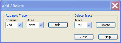
Add creates a new trace and adds it to the list in the Trace Manager, assigning it to the channel and diagram area selected in the drop-down lists. It is possible to create a New channel and/or diagram area for the new trace.
Delete deletes the selected trace, removing it from the list in the Trace Manager and from the screen. This button is disabled if the setup contains only one trace: In manual control, each setup must contain at least one diagram area with one channel and one trace.
Selects common channel or scale settings for all traces in the Trace Manager dialog.
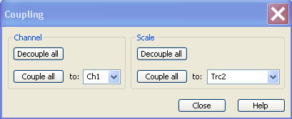
The channel and scale coupling is set in two independent panels.
Decouple All assigns independent channel or scale settings to all traces in the Trace Manager. If the channel and trace names include numbers, the trace with the lowest number is assigned to the channel with the lowest number and so forth. Measurement or data traces and their associated memory traces are assigned to the same channel.
Couple All assigns all traces to the channel or scale settings selected in the corresponding drop-down lists. All channel or scale settings except the selected ones are lost. The analyzer displays a confirmation dialog box before deleting the unused channels.
|
Remote control: |
– |
Changes the order of the traces (table rows) in the Trace Manager dialog.
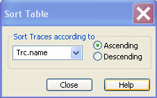
The drop-down list contains all trace properties that can provide the sorting criterion. The properties correspond to the column headers in the Trace Manager.
The two radio buttons qualify whether the traces in the table are sorted in ascending or descending order, according to the property selected in the pull-down list.
|
Remote control: |
No command, display configuration only. |